R3-TC2
5-2-55, Minamitsumori, Nishinari-ku, Osaka 557-0063 JAPAN
Phone: +81(6)6659-8201 Fax: +81(6)6659-8510 E-mail: [email protected]
EM-8468 Rev.3 P. 6 / 37
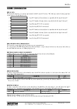
SYSTEM CONFIGURATIONS & CONTROL EXAMPLES
Relay
Oven
Heater Power
R3–BS
R3–NM3
R3–TC2
■
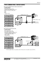
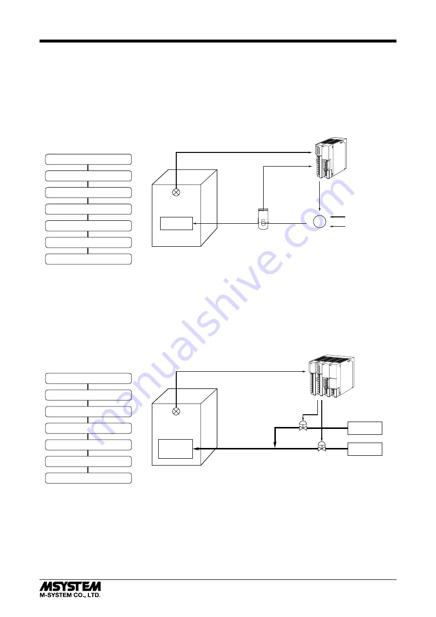
1 loop heating ON/OFF control and heater wire break detection
1. Installation example:
• Base (model: R3–BS)
• Interface Module (model: R3–NM3)
• Temperature Control Module (model: R3–TC2)
• Clamp-on Current Sensor (model: CLSE)
• Oven
• Heater
• Relay
• Temperature sensor
2. Proccess until start operating:
CLSE
Relay Power
CONTROL OUTPUT 3 (Do1)
UNIVERSAL INPUT 2 (Pv2)
CT INPUT 1
Ry
Heater
Turn ON power supply
Set input sensor type and range
Set CT input to wire break detection
Select control mode (ON/OFF Control)
Specify target temperature (SP)
Select operation mode (auto)
Start operation
Temp. Sensor
R3–BS
R3–PS1
R3–NM3
R3–TC2
R3–SV4
■
1 loop heating and cooling control (PID)
1. Installation example:
• Base (model: R3–BS)
• Power Supply Module (R3–PS1)
• Interface Module (model: R3–NM3)
• Temperature Control Module (model: R3–TC2)
• DC Voltage Input Module (model: R3–SV4)
(Other R3 modules also available)
• Object to heat/cool
• Temperature sensor
2. Proccess until start operating:
Control output 2 (Mv2)
Control output 1 (Mv1)
UNIVERSAL INPUT 1 (Pv1)
Object to
heat/cool
Cold water
Hot water
Select control mode (PID)
Set deadband
Specify target temperature (SP)
Select operation mode (auto)
Start operation
Temp. Sensor
Turn ON power supply
Set input sensor type and range
Note: The examples above are for single loop, however, dual loop control is also availabe using only one R3-TC2.


