Commissioning of the water sampling station
34
BA-42820-02-V03
Water sampling station
EASYPRO
Operating instructions
8.3.2.5 Analogue output signals
The basic configuration of the device includes up to four analogue 4 – 20
mA outputs. You can use the outputs to transmit the measured values to a
control room or a PLC (programmable logic controller).
Some actuators such as dosing pumps can be controlled directly via this
output.
Perform the following work steps:
1.
In the main menu under System > Outputs, navigate to the “Ana-
logue” tab.
2.
Working under “Analogue”, select the desired output.
3.
Configure the analogue output by entering the following data.
4. 20 mA type:
You can choose between the following signal types:
4 – 20 mA, 0 – 20 mA, 20 – 4 mA or 20 – 0 mA.
5. Testsignal:
You can test the configuration of the analogue outputs.
Check the actuation on the external device.
6. Output:
Determine what should be outputted on the selected output.
You can choose between the measurement and temperature values
or outputs (controller outputs).
7. Minimum:
Determine a minimum value. The minimum value indi-
cates for which measured value the signal is the weakest.
8. Maximum:
Determine a maximum value. The maximum value indi-
cates for which measured value the signal is the weakest.
i
The values for “minimum” and “maximum” serve the scaling
of the analogue output signal. Example: Sensor 1 has a meas-
uring range of 0 − 10 mg/l. 4 − 20 mA was selected as the 20
mA type. If the complete sensor measuring range is to be cov-
ered by the analogue signal, 0 mg/l should be selected for
“Minimum” and 10 mg/l for “Maximum”. At 0 mg/l, a 4 mA
signal will be issued; at 10 mg/l a 20 mA signal will be issued.
ü
Configuration of the analogue outputs completed.
8.3.2.6 Actuation of the LEDs for the water sampling stations
Some water sampling stations have multiple LEDs which display whether
a water parameter is in the desired range. You can configure the actuation
of the LEDs.
Perform the following work steps:
1.
Working in the main menu under System > Outputs, navigate to the
“External LEDs” tab.
2.
Working under “LED”, select the desired LED.
3.
Configure the LED by entering the following data.
4. Function:
Select the reaction criteria for the LED. Selection of “Sam-
ple water shortage” standardly results in a green LED. If the digital
contact “Sample water shortage” is active, it will illuminate red. Fur-
ther options are the measured values of the sensor inputs 1 – 4.
5. Minimum and maximum:
If you have decided to use a measured
value, you must establish a minimum and a maximum value. The LED
will illuminate red if the minimum value is undercut or the maximum
value exceeded. It illuminates green between the values.
6. Testsignal:
You can test the configuration of the LEDs.
ü
Configuration of the external LED outputs completed.
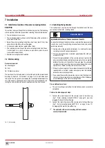
8.3.3 Second overview
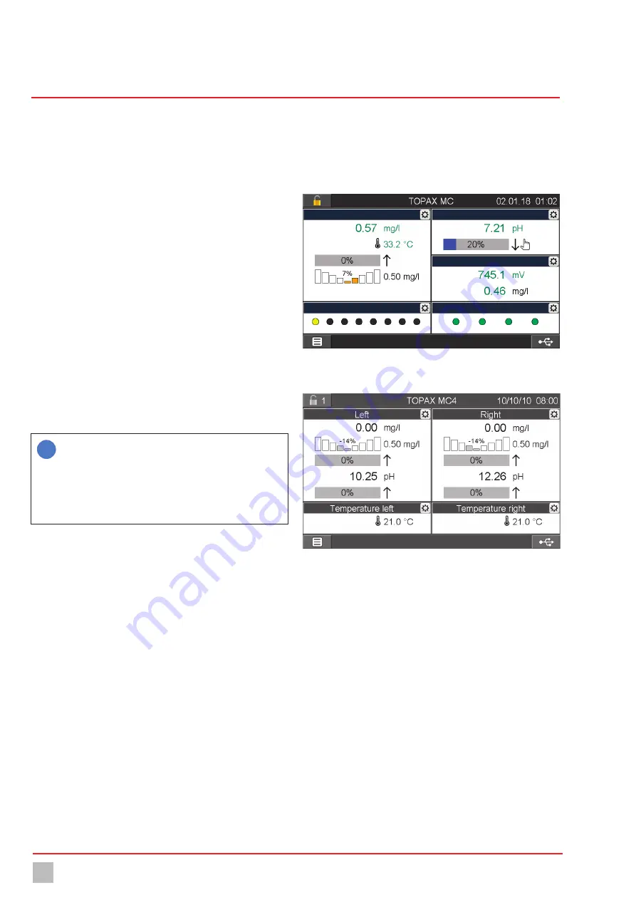
In the main view, the device shows the measured values of the installed
input modules. This display is pre-determined and cannot be changed.
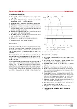
However, you can activate a “second overview” and adapt your needs in-
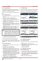
dividually (see Fig. 29 „Individual second overview“ on page 34).
Pool 1
Pool 3
Pool 2
LEDs
Digital inputs
Fig. 29: Individual second overview
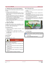
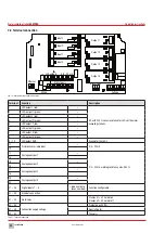
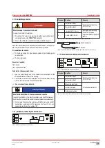
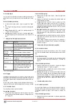
The second overview of the
EASYPRO
double versions
MBB
,
MEE
,
2/2
and
1/1
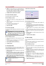
is preconfigured to provide a complete overview of all values.
Fig. 30: Second overview of an
EASYPRO
double version
8.3.3.1 Activating the second overview
Perform the following work steps:
1.
In the main menu under System > Settings, navigate to the “Display”
tab.
2. 2. Overview:
Activate the second overview with “On”.
3. Number windows:
Select how many individual and freely-configur-
able windows should be displayed.
ü
Second overview activated.
8.3.3.2 Configuring the second overview
Perform the following work steps:
1.
Press the “Main menu” button (bottom left on the display) until the
second overview with the individually-settable windows appears.
2.
A gear wheel icon is displayed in the top right-hand corner of every
window. Press on the icon to configure the selected window and
state the following information.
3. Name:
Give each window an individual name.

