


Installation
26
BA-42820-02-V03
Water sampling station
EASYPRO
Operating instructions
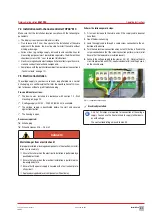
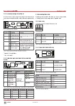
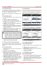
Testing the analogue outputs
You can also test the connection of terminals 13 to 20.
Pre-conditions for actions:
ü
The device housing cover is closed.
ü
The voltage supply has been established and the device has been
switched on.
Perform the following work steps:
1.
Working in the main menu, navigate to System > Outputs > Ana-
logue.
4
You will now see all analogue outputs (terminals 13 − 20).
2.
Press “Test signal”.
3.
Set the mA value.
4.
Press "Start”.
ü
Analogue outputs tested.
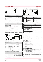
7.9 Digital inputs
You can use up to 8 digital inputs to evaluate switching statuses and to
detect them as alarm message which are to be documented in the log-
book.
Further information about the settings of the digital inputs can be found in
section 8.3.1.6 „Digital inputs“ on page 32.
7.10 RC protection for relay
When connecting to the relays, note that inductive loads must be sup-
pressed. If this is not possible, the relay contact on the device terminal
must be protected by an RC protective circuit / interference suppression
element.
Thus, the device will operate in an uncontrolled manner. To prevent bond-
ing if the load circuit suffers a short-circuit, the relays must be protected
separately on the maximum relay switching current.
Pre-conditions for actions:
ü
You would like to connect an inductive load to the relay.
Perform the following work steps:
1.
Switch off the device.
2.
Clamp the interference suppression element parallel to the inductive
load.
3.
Should it prove impossible to perform point 2, clamp the interference
suppression element parallel to the relay output.
ü
RC protection for relay connected.
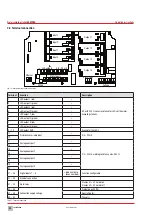
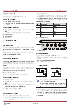
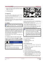
7.11 Connecting Ethernet
You can use the Ethernet connection for the following actions:
n
Reading/writing via Modbus TCP/IP protocol (PLC or Computer)
n
Access via web browser
n
Access via TFTP server
The device is fitted with a network input in the form or a 4-pole and
D-coded M12x1 socket. Lutz-Jesco GmbH offers different lengths of spe-
cial twisted-pair network cables to make the typical Ethernet RJ-45 plug
connection. If you use third-party cables, choose a Category 5 cable with
an impedance of 100 Ω or above.
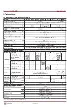
Pin
Assignments
Wire colours
1
TX-
yellow
2
TX+
orange
3
RX-
white
4
RX+
blue
-
Screen
-
Tab. 36: Ethernet connection socket
Fig. 25: Ethernet connection
Installing a wired network
During installation, comply with the following points:
n
The Ethernet is cabled in a star topology. The maximum cable length
is 100 m
n
Only use screened cables and connectors
n
Only use CAT5 cables or better
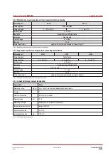
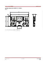
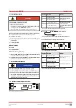
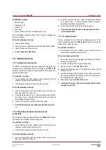
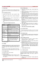
7.12 RS485 interface
Fig. 26: Jumper position on RS485
i
When using multiple devices on a data line you, must activate
a 120 Ω resistance on the last device.
You can activate the resistance by setting the jumper to “ON”
as shown in Fig. 26 „Jumper position on RS485“ on page
26.
Your device can have an optional RS485 interface. Using a second data
cable you can connect up to 14 devices with a PC or a PLC. Modbus RTU
protocol serves as a protocol for data transfer. You can use the addresses
1 to 14. The addresses 0 and 15 are reserved for internal purposes and
are not supported.
ON
OFF
A B
A B


