background image

Commissioning of the water sampling station

31

Subject to technical changes.
200114

BA-42820-02-V03

Water sampling station 

EASYPRO


Operating instructions

Perform the following work steps:

1. 

Working in the main menu under System > Inputs, navigate to the 
“Virtual” tab.

2. 

Working in the “Virtual” tab, configure the desired calculation of the 
bound chlorine and state the following information.

3.  Calculation:

 Select “bound chlorine” to calculate the bound chlorine.

4.  Total chlorine: 

Select the sensor which measures the total chlorine.

5.  Free chlorine:

 Select the sensor which measures the free chlorine. If 

no sensor is present, you can enter a reference value measured once 
which can be used for the calculation.

6.  Min-alarm:

 Activate or deactivate the minimum alarm and state a 

value under which the alarm will be triggered.

7.  Max-alarm:

 Activate or deactivate the maximum alarm and state a 

value over which the alarm will be triggered.

8.  Delay:

 Set a time delay for the minimum and maximum alarm.

ü 

Configuration of the bound chlorine completed.

Effective chlorine

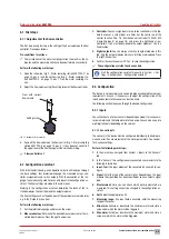
The disinfectant effect of the free chlorine is highly dependant on the pH 
value of the process water. The pH value influences the reactivity of the 
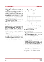
Chlorine ions. This relationship is underscored by the dissociation curve 
(Fig. 28 „Dissociation curve of the effective chlorine“ on page 31) of 
the chlorine.

The actual disinfectant effect of the chlorine is generated by the hy-
pochlorous acid (HClO). The figure shows that the proportion of the HClO 
is largest between pH 2 and pH 7.5. The disinfectant effect is very low 
outside this pH value.

For photometric measurements the pH value of the sample is buffered to 
approx. pH 6.5. As a result the measurement has a higher effective chlo-
rine content than is actually in the process water. For high pH-values sig-
nificant differences will therefore occur between the expected and actual 
disinfection if assessed by photometric analysis. The calculation of the ef-
fective chlorine can be used to display the proportion of the hypochlorous 
acid (HCIO), i.e. the proportion which contributes to the disinfectant effect.

100 % 

50 

10 

0,5 

0,1 

HCIO 

CIO- 

-.. 

.,,.. 

-----

-..

..... 

\/ 

� 

10 

12 

pH  >  1,7  :  Cl2 

H2O �  HCIO 

HCI 

pH  >  7,5  :  HCIO �  H

CIO-

14 

(pH) 

Fig. 28:  Dissociation curve of the effective chlorine

Perform the following work steps:

1. 

Working in the main menu under System > Inputs, navigate to the 
“Virtual” tab.

2. 

Working in the “Virtual” tab, configure the desired calculation of the 
effective chlorine and state the following information.

3.  Calculation:

 Select “effective chlorine” to calculate the effective 

chlorine.

4.  Free chlorine: 

Select the sensor which measures the free chlorine.

5.  pH value:

 Select the sensor which measures the pH value. If no sen-

sor is present, you can enter a reference value measured once which 
can be used for the calculation.

6.  Temperature: 

A temperature value is required to calculate the effec-

tive chlorine. Select the temperature input which can be used for the 
calculation. If no temperature sensor is present, you can set a refer-
ence value measured once which can be used for the calculation.

7.  Min-alarm: 

Activate or deactivate the minimum alarm and state a 

value under which the alarm will be triggered.

8.  Max-alarm:

 Activate or deactivate the maximum alarm and state a 

value over which the alarm will be triggered.

9.  Delay:

 Set a time delay for the minimum and maximum alarm.

ü 

Configuration of the calculation of the effective chlorine 

completed.

Содержание Jesco EASYPRO

Страница 1: ...ontrol Liquids Gases Systems Lutz Jesco GmbH 2020 BA 42820 02 V03 Water sampling station EASYPRO Operating instructions Read the operating manual The user is responsible for installation and operation...

Страница 2: ......

Страница 3: ...3 4 MC C MD C MP C MK C 18 6 3 Water sampling station EASYPRO 1 1 2 2 MBB C MEE C 19 7 Installation 20 7 1 Installation location of the water sampling station EASYPRO 20 7 2 Wall mounting 20 7 3 Insta...

Страница 4: ...ers to a potentially hazardous situation Failure to follow this instruction may lead to death or se vere injuries CAUTION Refers to a potentially hazardous situation Failure to follow this instruction...

Страница 5: ...n Failure of required maintenance and repair methods n Risk to persons when working on the device n Danger to the environment from overdosing 2 3 Working in a safety conscious manner Besides the safe...

Страница 6: ...ntion 2 4 3 Trained persons Trained persons have received training from the operator about the tasks they are to perform and about the dangers stemming from improper be haviour Trained persons have at...

Страница 7: ...applications and can be deployed universally Its main application is to maintain the quality of water by evaluating the measurements of chlorine value pH value and Redox value as well as conductivity...

Страница 8: ...Buffer solutions for adjusting each measuring cell The measuring cells are packaged separately and not pre installed 4 2 Design and function The water sampling station can continuously measure the lev...

Страница 9: ...function here external stop 3 Parameter calculated here effective chlorine 4 Module for pH and Redox single rod measuring cells Control system 1 Controller 1 2 Controller 2 1 Controlling the free chlo...

Страница 10: ...e g conductivity measuring cell 11 buffer solutions 12 Outflow tap Tab 5 Position numbers water sampling station EASYPRO 4 4 3 1 Main view The main menu view will appear upon the start of the product...

Страница 11: ...P N S N 42820005 2 1 3 6 4 5 EASYPRO Fig 5 Rating plate water sampling station EASYPRO No Position 1 Product name 2 Technical specification 3 WEEE label 4 Serial number 5 Part number 6 Month year of m...

Страница 12: ...nding on version Number of measuring inputs 2 3 4 3 2 x 2 Free chlorine Amperometric 3 electrode measuring cell with potentiostat DMZ3 1 mg l 0 15 dependant on the meas uring cell transcon ductance 0...

Страница 13: ...Amperometric 3 electrode measuring cell with potentiostat DMZ3 1 mg l 0 15 dependant on the measuring cell transconduct ance 2 x 0 15 dependant on the measuring cell transconductance CS120 excess chlo...

Страница 14: ...e with KCI gel filling Counter electrode Precious metal Copper Silver Measuring range 0 15 mg l Cl2 0 20 mg l Cl2 0 20 mg l Cl2 Transfer slope 20 30 A mg l Electrolyte Sample water Electrical connecti...

Страница 15: ...asuring total chlorine Measuring cell GCM GCM GCM Measuring input Total chlorine Measuring range 0 2 mg l Clges 0 5 mg l Clges 0 10 mg l Clges Transfer slope 4 20 mA Electrolyte Diaphragm cap with ele...

Страница 16: ...5 dependant on the measuring cell transconductance CS120 excess chlorine measuring cell mg l 0 10 dependant on the measuring cell transconductance Diaphragm covered measuring cell mg l 0 10 dependant...

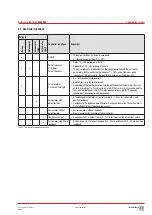
Страница 17: ...output e g for solenoid valve n Depending on the control deviation and the defined control parameters the relay pulls in or drops out for the set cycle duration If the cycle lasts 30 seconds and the c...

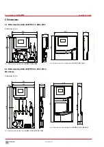
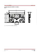
Страница 18: ...sampling station EASYPRO 3 4 MC C MD C MP C MK C All dimensions in mm Fig 8 Dimensions water sampling stations EASYPRO 3 4 MC C MD C MP C MK C 500 42820001_5 Ma bild Messwassertafel EASYPRO 2 mit Abde...

Страница 19: ...changes 200114 BA 42820 02 V03 Water sampling station EASYPRO Operating instructions 6 3 Water sampling station EASYPRO 1 1 2 2 MBB C MEE C 10 117 874 900 200 490 464 Fig 11 Dimensions water sampling...

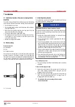
Страница 20: ...station PLEASE NOTE Hydraulic distortion of the measurement results Incorrectinstallationofthehydrauliclinescandistortthemeasurement results As a result the controlling of connected systems and contr...

Страница 21: ...is available The voltage supply is deactivated before the start and secured against reactivation The housing is open Resources required Schuko plug Wire end sleeves 0 75 2 5 mm DANGER Mortal danger f...

Страница 22: ...utput 3 green 7 LED output 4 red 8 LED output 4 green 9 10 LED output GND Ground for the LEDs 11 Disturbance variable input 0 4 20 mA 12 13 Analogue output 1 0 4 20 mA working resistance max 500 14 15...

Страница 23: ...nic distortion of the measurement results Incorrect installation of the electrical cables can distort the measure mentresults Asaresult thecontrolofconnecteddevicescanbefaulty Do not route the connect...

Страница 24: ...1 black BK 2 Temperature input blue BU 3 Conductivity measurement input brown BN 4 Conductivity measurement input white WH Tab 25 Terminal connection of the conductive input circuit board to the condu...

Страница 25: ...20 mA The output connects a servomotor with or without feedback 3 2 1 Fig 24 Output circuit board with servomotor 20 mA Terminal Function Description 1 GND 2 Input feedback 4 20 mA 3 Output 4 20 mA T...

Страница 26: ...parallel to the inductive load 3 Should it prove impossible to perform point 2 clamp the interference suppression element parallel to the relay output RC protection for relay connected 7 11 Connectin...

Страница 27: ...ivity The connecting cables are already installed on the TOPAX MC controller and need only be connected to the measuring cells Pre conditions for actions The installation of the water sampling station...

Страница 28: ...arameters n With a control output power of Y 25 and a maximum pulse frequency of 100 pulses min the controller would output 25 pulses min x Pulse length 2 sides pulse length n 0 3600 seconds cycle dur...

Страница 29: ...or a timer Set the centre row of the control function Tab 18 Multi channel controller TOPAX MC measuring inputs on page 16 and press the right hand arrow Controllers 1 to 4 must be assigned to the out...

Страница 30: ...e calculation Example If the factor 2 and the disturbance variable amounts to 42 the controller can be set to a maximum of the control variable Y 84 If the factor 0 5 and the disturbance variable amou...

Страница 31: ...surement has a higher effective chlo rine content than is actually in the process water For high pH values sig nificant differences will therefore occur between the expected and actual disinfection if...

Страница 32: ...ntroller tab 2 Working in the Controller tab configure the controller output and state the following information 3 Y alarm Activate the Y alarm The Y alarm is a safety cut out If the controller output...

Страница 33: ...steps 1 In the main menu under System Outputs navigate to the Digital tab 2 Working under Digital output select the desired output 4 The free outputs will be displayed which you have configured as an...

Страница 34: ...Ds Perform the following work steps 1 Working in the main menu under System Outputs navigate to the External LEDs tab 2 Working under LED select the desired LED 3 Configure the LED by entering the fol...

Страница 35: ...puts and outputs and the adjust ment of the sensors are accessible here This level is required for de vice configuration and should only be operated by experienced users n 3 Level The service menu is...

Страница 36: ...book i You can open and analyse CSV files with a suitable programme e g MS Excel You can also view all CSV files on the device 9 2 1 View and open files You can display the logbook files on the device...

Страница 37: ...ells 1 and 3 for the left hand area Select measuring cells 2 and 4 for the right hand area Fig 32 View of the EASYPRO water sampling station as a double version 9 5 2 pH single rod measuring cell Cali...

Страница 38: ...the entry with the green checkmark 1 point adjustment of the pH value completed 9 5 2 3 Offset compensation External influences can cause the pH value measured with the photome ter to deviate from th...

Страница 39: ...y present The sensor is operated with sample water Perform the following work steps 1 Working in the main menu under Calibration navigate to the Sen sors tab 2 Working under Sensor select the sensor t...

Страница 40: ...in the main menu under Calibration navigate to the Sen sors tab 2 Working under Sensor select the sensor that measures the con ductivity and which you wish to calibrate 3 Press the 1 points button 4...

Страница 41: ...servomotor is switched on and has been connected properly The output has been configured correctly see Tab 20 Functions of the individual controllers on page 17 Perform the following work steps 1 Work...

Страница 42: ...points menu item navigate to the Switching tab Set a checkmark against Switch setpoints automatically 2 Working in the Manual mode menu set a checkmark against Switch setpoints automatically You can u...

Страница 43: ...he reference sets Set a checkmark here 2 Switch over Configure up to ten timer switches and state the fol lowing information 3 Off Active Switch on the timer 4 Time Configure a time at which the switc...

Страница 44: ...ling station EASYPRO 4 on page 10 pos 3 as well as the outgoing hose connection from the outflow tap Fig 2 Water sampling station EASYPRO 4 on page 10 pos 12 and the measuring cell valve 5 Unscrew the...

Страница 45: ...roller Tab 41 Maintenance intervals 11 2 Finishing maintenance Perform the following work steps 1 Make a note of the date and scope of the maintenance performed 2 In the Service menu navigate to the S...

Страница 46: ...ow controller and open carefully 4 Replace all the O rings in the flow controller Lightly grease all the new O rings with silicone grease before insertion 5 Replace the diaphragm 6 Check all further c...

Страница 47: ...2 Using the socket wrench unscrew the retaining nuts from the white protective plate and remove the plate 3 Using the socket wrench unscrew the two nuts from the input circuit boards which you need to...

Страница 48: ...factory set configuration file unchanged and save your personal configuration in a new file Given problems with the configuration this enables you to return to a functioning configuration quickly Per...

Страница 49: ...ample water inflow is soiled Check the visible parts and filter Fig 2 Water sampling station EASYPRO 4 on page 10 pos 3 for soiling and clean if necessary The LEDs are continually red The controller d...

Страница 50: ...and use other chemicals for disinfection The TOPAX MC controller loses all settings after he has been disconnected from the network and then recon nected The battery is empty n Check that the battery...

Страница 51: ...ss 2002 0x3536 transferred 2003 x Status of digital inputs Displays the terminal logic not the configured software function The individual bits are assigned directly to the input clamps Example 0x01 m...

Страница 52: ...5 No type 2021 2022 x Measurement Number of positions after the decimal point see unit 4 bytes signed int 2023 x Unit Number Unit decimal places 0 1 2 3 4 5 6 7 8 9 10 11 12 13 14 mA A ppm mg l S cm m...

Страница 53: ...x x Minimum and maximum alarm Write 0 clear alarm Read Bit 0 minimum alarm is active Bit 1 maximum alarm is active 2035 x x Y alarm Write 0 clear alarm Read Bit 0 Y alarm is inactive Bit 1 Y alarm is...

Страница 54: ...ual mode 2107 2108 x x Setpoint 1 Number of positions after the decimal point see unit 4 bytes signed int 2109 2110 x x Setpoint 2 If 2 side control is active 4 byte signed int 2111 x x Xp Number of p...

Страница 55: ...um alarm Sensor 1 minimum alarm Sensor 2 minimum alarm Sensor 3 minimum alarm Sensor 4 minimum alarm 0 1 2 3 4 5 6 7 8 9 10 11 12 13 14 15 2226 x Alarm status 2 If the bit is set the associated alarm...

Страница 56: ...put 7 Digital input 8 Sensor 1 calibration not OK Sensor 2 calibration not OK Sensor 3 calibration not OK Sensor 4 calibration not OK Temperature 1 calibration not OK Temperature 2 calibration not OK...

Страница 57: ...manufactured in accordance with valid good engineering practice In accordance with article 4 section 3 as a pressure device the EASYPRO does not carry CE marking and cannot be issued with a EU dec lar...

Страница 58: ...requisitos sanitarios y de seguridad vigentes de las directivas de la U E citadas a continuaci n Esta declaraci n ser invalidad por cambios en el aparato realizados sin nuestro consentimiento 2014 30...

Страница 59: ...es No Properties Corrosive Yes No We hereby certify that the product has been cleaned thoroughly inside and outside before returning that it is free from hazardous material i e chemical biological tox...

Страница 60: ...one Date Address Contact person Manufacturer order no Date of delivery Device type Serial number Nominal capacity nominal pressure Description of fault Service conditions of the device Point of use sy...

Страница 61: ...ional range Xp The proportional range Xp p proportion of a P PI or PID controller indi cates the amount by which the actual value X must deviate from the setpoint W so that the variable Y 100 If the c...

Страница 62: ...value control 33 Logbook 37 Long term shut down 45 M Maintenance 46 Measuring cells 14 Open 3 electrode measuring cell 14 N Notes for the Reader 4 O Operation 37 P Personnel qualification 5 Personnel...

Страница 63: ......

Страница 64: ...Copyright 2020 by Lutz Jesco GmbH Lutz Jesco GmbH Am Bostelberge 19 D 30900 Wedemark Phone 49 5130 5802 0 info lutz jesco com www lutz jesco com Operating instructions Water sampling station EASYPRO...

Отзывы: