Installation
25
Subject to technical changes.
200114
BA-42820-02-V03
Water sampling station
EASYPRO
Operating instructions
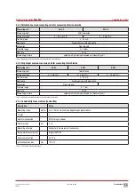
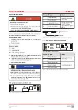
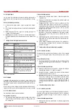
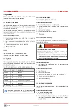
7.8.3 Output circuit board with optocoupler
4
3
2
1
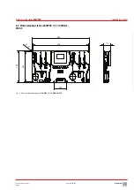
Fig. 22: Output circuit board with optocoupler
Terminal Function
Description
1
+
Optocoupler x 2
Second digital output
2
-
3
+
Optocoupler x 1
First digital output
4
-
Tab. 30: Clamp connection of the output circuit board with optocoupler
Actors
Configuration
MAGDOS dosing pumps
Pulse frequency
MEMDOS dosing pumps
MEMDOS SMART dosing pumps
Tab. 31: Actors and configuration optocoupler
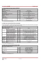
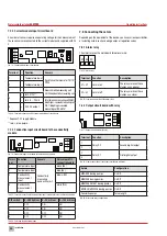
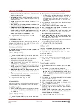
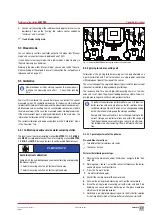
7.8.4 Servomotor relay output circuit board
This output is suitable for connecting a servomotor with or without feed-
back via a potentiometer from 1 – 10 kΩ.
3
2
1
6
5
4
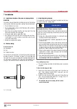
Fig. 23: Servomotor relay output circuit board
Terminal Function
Description
1 − 2
Opening the regulation
valve
Relay output
2 − 3
Closing the regulation valve Relay output
4
Feedback via potentiometer
5
6
Tab. 32: Clamp connection of the output circuit board with servomotor relay
Actors
Configuration
Chlorine gas control valve C 7700
Servomotor with potentiometer/
servomotor without potentiometer
Tab. 33: Actors and configuration servomotor relay
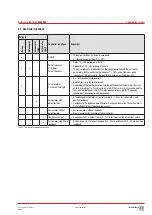
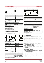
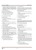
7.8.5 Output circuit board with servomotor 20 mA
The output connects a servomotor with or without feedback.
79829_1
Bild BA Ausgangsmodul ATE (20 mA) mit Rückmeldung
EASYCON
3
2
1
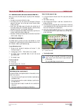
Fig. 24: Output circuit board with servomotor 20 mA
Terminal Function
Description
1
-
GND
2
Input (feedback)
4 − 20 mA
3
Output
4 − 20 mA
Tab. 34: Clamp connection of the output circuit board with servomotor 20mA
Actors
Configuration
Chlorine gas control valve C 7700
Servomotor with 20 mA/
continuous output (20 mA)
EASYZON chlorine dioxide system
Continuous output (20 mA)
MAGDOS dosing pumps
MEMDOS dosing pumps
MEMDOS SMART dosing pumps
Tab. 35: Actors and configuration servomotor 20 mA
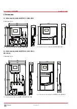
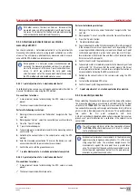
7.8.6 Testing the outputs
You can use manual mode to test the correct connection of an actor.
Take the alarm chain into account before conducting the test and inform
any connection points or interrupt the alarm chain for the period of the
test.
Test the connected actors
Pre-conditions for actions:
ü
The actors have been connected in accordance with section 7.8
„Connecting the actors“ on page 24.
ü
The device housing cover is closed.
ü
The voltage supply has been established and the device has been
switched on.
Perform the following work steps:
1.
Working in the main menu, navigate to “Manual mode” (see section
9.4 „Manual mode“ on page 37).
4
You will now see all the outputs.
2.
Select the output to which you have connected the actor and which
you wish to test.
3.
Enter a value between 0 and 100 % and check whether the actor re-
acts as desired.
ü
Actor has been tested.
0%
100%

