®
Wallbox Power Module Installation and Operation Guide 5
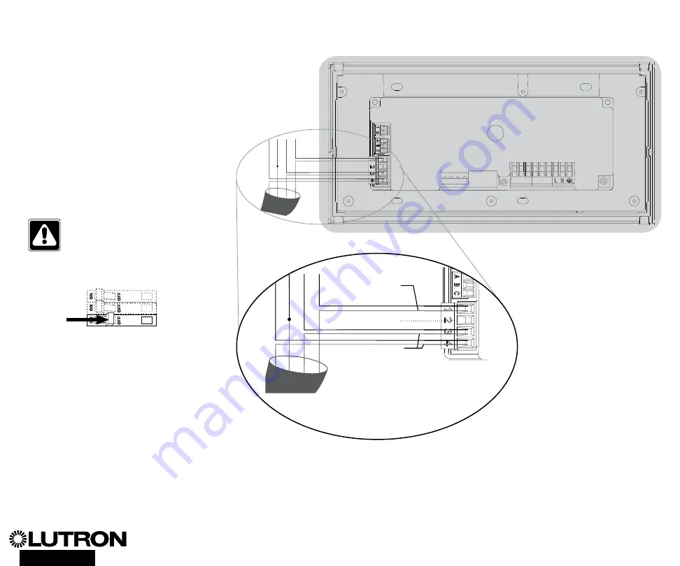
Wiring the Wallbox Power Module with DALI Control Unit:
IEC PELV/NEC
R
Class 2 Wiring Details (HomeWorks
R
QS only)
The WPM can be configured for wired/QS
link (HomeWorks
R
QS only) or wireless/
RF link (RadioRA
R
2 and HomeWorks
R
QS) communication. The following
diagram illustrates wiring the device to
a QS link. HomeWorks
R
QS supports
selection of wired or RF communications.
A Wallbox Power Module main unit that
communicates back to a HomeWorks
R
QS processor through the RF link should
not have any QS wired link connections.
In RadioRA
R
2 only RF communication is
available
WARNING!
Shock hazard.
May
result in serious injury or death.
Always turn off circuit breaker or
remove main fuse from power line
before doing any work.
Step 1:
Strip 25 mm of insulation from
the IEC PELV/NEC
R
Class 2 cable.
Step 2:
Strip 7 mm of insulation from
each wire in the cable.
Step 3:
Connect the wires to the QS Link
terminal block, making sure no bare wire
is exposed after making the connections.
The recommended installation torque is
0.4 N
•
m for QS Link connections.
ON
OFF
ON
OFF
ON
OFF
Note:
The QS Link IEC PELV/NEC
R
Class 2 cable and terminal block should be
separated from the DALI Link wires.
D1 D1 D2 D2
Data link: twisted, shielded pair
0.34 mm
2
to 0.75 mm
2
DO NOT CONNECT PIN 2
IEC PELV / NEC
R
Class 2 control
wiring: 0.75 mm
2
HomeWorks
R
QS Link 610 m
maximum total wire length
per run
Pin 2 does not get connected to the
WPM – it does not require link power
To additional QS devices
D1 D1 D2 D2
Note:
The QS Link IEC PELV/NEC
R
Class 2 cable and terminal block should
be separated from the line voltage/mains
cables by at least 6 mm.


