Lucent Lineage
®
2000 ECS Battery Plant H569-408
3 - 12 Installation
Issue 2 July 1996
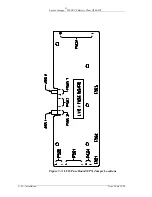
Run paired leads (supply and return) to each load from a dc
distribution circuit breaker and from the discharge return bus.
The load supply leads are terminated at the battery plant end on
terminal blocks TB701 on the distribution printed wiring boards.
The load return leads are terminated at the battery plant end on
the discharge return bus, directly above the load supply lead
termination. The termination points for the load leads are
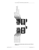
numbered 1 to 42, from right to left. Distribution breaker
positions are also numbered 1 to 42, from left to right.
To install a circuit breaker, first verify that the circuit breaker is
in the OFF position. Plug in the circuit breaker and visually
verify that the line, load, and alarm connections are properly
mated. (See Figure 2-4). Remove the plastic knockout from the
associated position on the front cover. Mark the new circuit on
the distribution front cover label. Spare circuit breakers may or
may not be provided with the dc distribution panel, as ordered.
Spare circuit breakers maybe stored in distribution panel if in the
OFF position. Leads may be run to spare circuit breaker
positions in anticipation of future growth (similarly to prewiring
rectifier ac input in Step E, above).
Recommendations for routing and dressing of load leads as they
leave the battery plant and enter the cable rack system is shown
on the plant assembly drawing, H569-408. Consult the job
application drawings for the routing of these leads to the load
equipment. A label is provided on the dc distribution cover that
may be marked to indicate each load breaker's use.
Before proceeding, verify that all load circuit breakers are in the
OFF position.
Step H: Initial Charge
Batteries may undergo initial charging at this time, according to
the manufacturer's recommendations. One of the rectifiers may
be used for initial charging. Refer to the procedures given in the
Battery and Rectifier manuals.
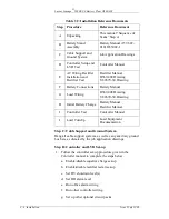
Step I: Controller Test
Follow the controller test procedure given in the ECS controller
manual to complete the steps below.
1. Test Enable/disable equalize charge feature.
2. Test Enable/disable rectifier restart feature.
3. Test HV shutdown level(s).


