background image

Configuring the Shelf Controller

Providing a basic system IP configuration

APX 1000™ Getting Started Guide

 5-11

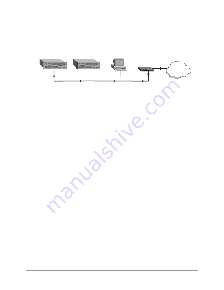
Figure 5-5.  Local router to be used as default route

Assuming a local router as the unit’s default route, or gateway, enables the APX 1000 unit to 
pass all IP packets with an unrecognized address to that router, so its own routing tables can 
remain small. The external router maintains larger routing tables, and assumes the 
responsibility and overhead of routing most packets.

For example, the following commands define a default route to the LAN router in Figure 5-5:

admin> new ip-route default

IP-ROUTE/default read

admin> set gateway-address = 1.1.1.3

admin> set active-route = yes

admin> write

IP-ROUTE/default written

The system can support multiple default routes. The profile name does not have to be 

default

. The only requirements are that the destination address must be zero, and Gateway-

Address must specify a valid, accessible router.

For information about other settings in the IP-Route profile, see the APX 8000™/MAX TNT® 
Reference
.

Verifying an administrative LAN connection

To enable yourself and other administrators to log into the APX 1000 unit’s interface from IP 
hosts, you must also make sure your local network can route to the unit. Your network router 
must have network connectivity through intermediate routers so that the administrative host 
can access the APX 1000 unit via its IP address. You can test this connectivity by pinging the 
unit from the local host. For example, the following command entered on a local host tests 
connectivity to the APX 1000 address, configured previously:

ping 1.1.1.1

PING 1.1.1.1 (1.1.1.1): 56 Data bytes

64 bytes from 1.1.1.1: icmp_seq=0 ttl=255 time=0 ms

64 bytes from 1.1.1.1: icmp_seq=7 ttl=255 time=0 ms

^C

--- 1.1.1.1 Ping statistics ---

8 packets transmitted, 8 packets received, 0% packet loss

round-trip min/avg/max = 0/0/0 ms

Traffic with unknown destination addresses

Ethernet

APX 1000

APX 1000

Computer

Router

WAN

Содержание APX 1000

Страница 1: ...APX 1000 Getting Started Guide Part Number 7820 0834 006 For software version 10 1 March 2004 ...

Страница 2: ... official Declaration of Conformity certificate for this equipment according to EN 45014 access the Lucent INS online documentation library at http www lucentdocs com ins Safety compliance and warranty Information Before handling any Lucent Access Networks hardware product read the Edge Access and Broadband Access Safety and Compliance Guide included in your product package See that guide also to ...

Страница 3: ...mber Software and hardware options If supplied by your carrier service profile identifiers SPIDs associated with your line Your local telephone company s switch type and operating mode such as AT T 5ESS Custom or Northern Telecom National ISDN 1 Whether you are routing or bridging with your Lucent product Type of computer you are using Description of the problem Obtaining assistance through email ...

Страница 4: ......

Страница 5: ... installation site 2 3 Required installation tools and equipment 2 3 Understanding the unit s back panel 2 3 Understanding the shelf controller back panel 2 4 Shelf controller connectors and slots 2 4 Shelf controller status lights 2 5 Understanding power supplies 2 6 ac power supplies 2 6 dc power supplies 2 7 Understanding APX 1000 slot cards 2 7 Ingress slot cards 2 7 DSP slot cards 2 7 Egress ...

Страница 6: ...X 1000 management features 4 2 Using the command line interface 4 2 Onboard flash memory and software updates 4 3 RADIUS support 4 3 Tracking system activity 4 3 Verifying slot card operation 4 4 Chapter 5 Configuring the Shelf Controller 5 1 Shelf controller configuration overview 5 1 Administrative connections 5 1 Serial connection to a console 5 1 Network connection to a workstation console 5 2...

Страница 7: ...hernet 3ND status indicators B 10 Ethernet 3ND technical specifications B 10 Ethernet 3 slot card B 11 Status indicators B 11 Specifications B 11 APX Ethernet card B 12 Status indicators B 12 Specifications B 13 DS3 ATM2 card B 13 DS3 ATM2 status indicators B 13 DS3 ATM2 technical specifications B 14 OC3 ATM2 card B 15 SWAN2 slot card B 18 Appendix C Cabling and Connector Specifications C 1 Serial...

Страница 8: ...o RJ 48C C 11 E1 PRI straight through cable RJ 48C to DA 15 C 12 E1 PRI crossover cable RJ 48C to DA C 13 E1 PRI straight through cable RJ 48C to Bantam C 14 E1 PRI WAN connector pins C 15 Appendix D Safety Related Electrical Physical and Environmental Information D 1 Electronic and electrical specifications D 1 Battery D 1 Electrical requirements D 2 Ground wire size D 2 Governmental notices D 3 ...

Страница 9: ...cable to an APX 1000 unit 3 12 Figure 3 13 Connecting an Ethernet cable 3 13 Figure 3 14 Verifying the presence of a PCMCIA card in slot 1 3 13 Figure 3 15 Wrist strap grounding 3 15 Figure 3 16 Rear connector examination 3 16 Figure 3 17 Inserting a slot card 3 16 Figure 3 18 Tightening the jack screw 3 17 Figure 3 19 Tightening the lock screw 3 17 Figure 3 20 Front cover notches 3 18 Figure 3 21...

Страница 10: ...lot card B 19 Figure C 1 RJ 48C to RJ 48C crossover cable C 4 Figure C 2 RJ 48C to RJ 48C straight through cable C 5 Figure C 3 RJ 48C to DB 15 straight through cable C 6 Figure C 4 RJ 48C to DB 15 crossover cable C 7 Figure C 5 RJ 48C to Bantam straight through cable C 8 Figure C 6 RJ 48C to RJ 48C crossover cable C 10 Figure C 7 RJ 48C to RJ 48C straight through cable C 11 Figure C 8 RJ 48C to D...

Страница 11: ...thernet 3 slot card status indicators B 11 Table B 12 Ethernet 3 card specifications B 11 Table B 13 APX Ethernet status lights B 12 Table B 14 APX Ethernet slot card specifications B 13 Table B 15 DS3 ATM2 card status indicators B 13 Table B 16 DS3 ATM2 card specifications B 14 Table B 17 OC3 ATM2 status lights B 16 Table B 18 OC3 ATM2 copper card specifications B 16 Table B 19 OC3 ATM2 Short Hau...

Страница 12: ...J 48C to Bantam straight through cable specifications C 14 Table C 15 Transmit and Receive pins C 15 Table D 1 APX 1000 electrical requirements D 2 Table D 2 Ground wire size D 2 Table D 3 APX 1000 physical specifications D 3 Table D 4 APX 1000 site specifications D 4 ...

Страница 13: ...ation about configuring the unit for Asynchronous Transfer Mode ATM frame relay or routing and tunneling services see the APX 8000 MAX configuration guides listed under on Documentation set on page xv Note This manual describes the features for APX 1000 units running software version 9 1 149 Some features might not be available with earlier versions or specialty loads of the software What you shou...

Страница 14: ...nal argument you might add to a command To include such an argument type only the information inside the brackets Do not type the brackets unless they appear in boldface Separates command choices that are mutually exclusive Points to the next level in the path to a parameter or menu item The item that follows the angle bracket is one of the options that appear when you select the item that precede...

Страница 15: ... attributes and how to create permanent virtual circuit PVC and switched virtual circuit SVC ATM interfaces It includes information about ATM direct and ATM frame relay circuits APX 8000 MAX TNT Frame Relay Configuration Guide Describes how to configure frame relay operations on a TAOS unit This guide explains physical layer configuration and restrictions and how to create permanent virtual circui...

Страница 16: ...Guide About This Guide Documentation set Reference APX 8000 MAX TNT Reference An alphabetic reference to all commands profiles and parameters supported on TAOS units TAOS Glossary Defines terms used in documentation for TAOS units ...

Страница 17: ...ons using SS7 IPDC is supported ASGCP is not supported The APX 1000 supports switched and leased line connections and analog and digital user sessions The unit complies with existing standards for networks authentication and Simple Network Management Protocol SNMP management The APX 1000 chassis is available in four configurations to meet the requirements of different environments T3 supports up t...

Страница 18: ...ections to the APX 1000 One egress slot card that passes combined subscriber traffic onto a backbone network Up to three digital signal processor DSP slot cards or two DSP slot cards if a slot is used for a second E1 ingress card Dual ac or dc power supplies Slot cards in an APX 1000 unit connect to each other via the backplane The shelf controller manages the system and interacts with the slot ca...

Страница 19: ...urations Table 1 2 lists the slot cards supporting the primary configurations of an APX 1000 unit and identifies the port speed and port capacity for each card type For detailed slot card descriptions see Appendix B Slot Card Specifications Table 1 1 APX 1000 primary configurations and slot cards Configuration Ingress slot card s Egress slot card DSP slot cards T3 Channelized T3 card 2 port Ethern...

Страница 20: ...Mbps One active port 672 DS0 channels and one bypass port Slot 5 Ethernet 3ND 10 100Mbps Four autosensing 10 100Mbps ports RJ 45 connectors Slots 1 to 4 Ethernet 3 10 100Mbps One autosensing 10 100Mbps port RJ 45 adapter required Slots 1 to 4 APX Ethernet 10 100Mbps Two autosensing 10 100Mbps ports RJ 45 connectors Slots 1 to 4 MultiDSP 96 ports N A 96 ports that can be used as voice ports data po...

Страница 21: ...it components This strap should be connected to ground potential For information about installing a slot card in a slot see Chapter 3 Installing an APX 1000 Chassis Table 1 3 APX 1000 slot cards for other configurations Card Port speed Port capacity Installation location DS3 ATM2 44 736Mbps One active and one bypass trunk connection Slot 1 to 4 OC3 ATM2 155 52Mbps One unchannelized OC 3 port Slot ...

Страница 22: ......

Страница 23: ...mon plastics and that you are properly grounded with an antistatic wrist strap to prevent component damage from electrostatic discharge For more information see Handling APX 1000 components on page 3 2 Before you install a APX 1000 unit make sure you have the following A suitable location with adequate power At least one active T1 or E1 line set up for bidirectional calling Bidirectional calling e...

Страница 24: ...Ethernet LAN connection for connecting the unit to the Ethernet network Blank single slot filler cards for any unused slots in the unit A blank power supply filler card if the unit is equipped with only a single power supply Checking the package contents APX 1000 package contents vary depending on the configuration of the unit you order After opening the package verify that you have all the system...

Страница 25: ...Environmental specifications on page D 4 Required installation tools and equipment To install APX 1000 hardware you need the following tools and equipment RS 232 straight through modem cable for connecting a PC or workstation to the unit ITE 6801 Antistatic wrist strap and mats ITE 4987C Number 2 Phillips screwdriver 1 8 inch standard screwdriver KS 6854 3 16 inch standard screwdriver R 5205 3 8 i...

Страница 26: ...oller Shelf controller connectors and slots Figure 2 3 shows the location and Table 2 2 describes the function of each element on the shelf controller Table 2 1 APX 1000 slot usage Slot ID Intended usage Supported slot cards 5 Incoming connections ingress 24 port T1 or E1 8 port E1 8 port T1 Channelized T3 1 to 4 Incoming connections ingress 8 port E1 narrow width 1 to 4 Signal processing support ...

Страница 27: ...ack panel element Function 10 100BaseT Ethernet port RJ 45 Ethernet port to connect an unshielded twisted pair UTP Ethernet LAN cable to the APX 1000 unit This connection is for the local administrative network PCMCIA slots Two flash PCMCIA slots for nonvolatile RAM NV RAM memory cards CONTROL port Female DB 9 connector for a serial connection to an administrative terminal or workstation Table 2 3...

Страница 28: ...nt AC power outlets you must use a local power cord that meets the following requirements The equipment end of the cable must connect to the APX1000 unit s standard C14 interface Must be rated 240 VAC at 8 AMPs Meets local safety approvals for example CE VDE CSA UL For additional requirements of and specifications for the ac power supply see Electrical requirements on page D 2 The ac power supply ...

Страница 29: ...Electrical requirements on page D 2 The APX 1000 dc power supply is shown in Figure 2 6 Figure 2 6 APX 1000 dc power supply The back panel of the dc supply has two status lights described in Table 2 4 Understanding APX 1000 slot cards The APX 1000 chassis has five slots that accept the following different types of slot cards These slots are visible in Figure 2 2 on page 2 3 All slot cards have a F...

Страница 30: ...n be installed in slots 1 to 4 DSP slot cards DSP cards support the processing of the line or modem protocols for the incoming connections These cards can occupy slots 1 through 4 although slot 1 is generally reserved for the egress card Egress slot cards Egress cards support connections to one or more networks for routing the data to and from the individual connections supported by the ingress ca...

Страница 31: ...is guide for information specific to your product Temperature guidelines for installing units in a rack or cabinet To ensure adequate cooling keep the following information in mind when installing APX 1000 units The maximum recommended ambient temperature for the APX 1000 unit is 50 Celsius 122 Fahrenheit Take care to allow sufficient air circulation when an APX 1000 unit is Temperature guidelines...

Страница 32: ...nents from electrostatic discharge always follow the proper guidelines for equipment handling and storage Modules slot cards and semiconductor devices in general can be easily and permanently damaged due to electrostatic discharge during installation or removal A person walking across a floor can generate electrostatic voltages in excess of 5000V Although you might not notice a discharge of less t...

Страница 33: ...e 3 2 Plugging the wrist strap into a grounding jack If a grounding jack is not available use an alligator clip to connect the strap to electrical ground Use the following two simple tests to verify that the wrist strap is functioning properly Measure the resistance between the wrist strap and its grounding plug Overall resistance between these two points must be approximately 1 megohm If the meas...

Страница 34: ...omponents Store components properly Protect slot cards and modules immediately after removal from a chassis by placing them in their original factory packing materials Storage in approved antistatic packaging is acceptable when factory packaging is unavailable Caution Never place unprotected slot cards or modules directly on ungrounded metal shelving or on ungrounded carts without insulating surfa...

Страница 35: ...t Then use four of the screws that are provided to attach the wide tab of each adapter to the sides of the unit When the APX 1000 unit is mounted in a 23 inch rack you must turn each adapter so that its wide tab faces toward the front of the unit Then use two of the screws that are provided to attach the narrow tab of each adapter to the sides of the unit Chassis mounting points There are three pa...

Страница 36: ...andling APX 1000 components on page 3 2 for details 1 Record the slot positions of each component and then remove all power supplies and slot cards from the APX 1000 chassis 2 Orient the mounting adapters with the long tab against the chassis and the short tab facing forward as shown in Figure 3 6 3 Align the holes in the mounting adapters with the screw holes in the chassis and attach the mountin...

Страница 37: ...o protect the cards from exposure to static electricity while they are removed from the chassis See Handling APX 1000 components on page 3 2 for details 1 Record the slot positions of each component and then remove all power supplies and slot cards from the APX 1000 chassis 2 Orient the mounting adapters with the short tab against the chassis and the longer tab facing forward as shown in Figure 3 ...

Страница 38: ...ies in the same slot locations from which they were removed Installing or replacing APX 1000 power supplies The APX 1000 has locations for two ac or dc power supplies Caution If only one power supply is used the unused position must be filled with a blank power supply module PN 1410 1291 001 shown in Figure 3 8 This blank module is required to maintain proper air flow for cooling the unit Figure 3...

Страница 39: ...ly on the handle loop on the power supply to disengage the connector within the APX 1000 chassis 4 Hold the old power supply level while sliding it out of the APX 1000 chassis 5 Align the new power supply being installed with the empty power supply slot in the chassis 6 Rest the guide rails located on both sides of the power supply on the guide tabs located on either side of the empty power supply...

Страница 40: ...ower supply switch is in the OFF left position To connect the ac power supply plug one end of the power cord into the socket on the power supply and the other end into an approved ac source Use solid copper 12 AWG 4 0mm2 wire to connect the chassis ground to the facility s ground If the APX 1000 unit is fed from an isolated power supply you must supply a solid ground to earth via copper rods This ...

Страница 41: ...connections are 48Vdc top terminal and Return 48Vdc common return bottom terminal The 48V and Return connections are isolated from ground Caution Before connecting power the APX 1000 chassis must be grounded See the Access Networks Safety and Compliance Guide for additional safety instructions and circuit regulatory information To connect power to an APX 1000 dc power supply 1 Remove the lexan cov...

Страница 42: ...port specifications on page C 1 Figure 3 12 Connecting a serial cable to an APX 1000 unit 2 If you have not already done so set the serial communication options of your communications software as follows 9600bps Direct connection 8 data bits No parity 1 stop bit No flow control Connecting an APX 1000 unit to a LAN All APX 1000 units have an Ethernet port on the shelf controller This Ethernet port ...

Страница 43: ...ry Caution You can remove and replace the PCMCIA card while the APX 1000 unit is operating However do not replace the PCMCIA card under the following conditions Doing so might abnormally terminate the operation in progress and result in a loss of data A system reset is in progress and all cards are not fully operational Code is being loaded from a TFTP server using the load command Configuration o...

Страница 44: ...e following example admin fsck 1 Volume Stats Block Size 512 typical 512 Blocks Per Cluster 16 typical 1 may be powers of 2 up to 16 Reserved Blocks 1 typical 1 but may be 0 hundreds Number of FATs 2 must be 2 Number of Root Directory Entries 512 typically between 32 and 224 Total Blocks 62592 Media Descriptor f8 ignored Volume Info calculated from values above Blocks Per Fat 12 Fat Start Block 1 ...

Страница 45: ... and for upgrade instructions see the most recent release notes For information about loading software on the APX 1000 unit and recovering from a failed slot card installation see the APX 8000 MAX TNT Administration Guide Installing an APX 1000 slot card To install a slot card in the APX 1000 chassis proceed as follows 1 Before handling slot cards or any other components that are sensitive to stat...

Страница 46: ...hat the panel is facing you and the lock screw is on the left and insert the card into the open slot as shown in Figure 3 17 Figure 3 17 Inserting a slot card 4 Push the card along the internal card guides until the jack screw on the right side of the card panel is seated in the hole in the back panel The panel of the slot card must be parallel to the back panel of the unit ...

Страница 47: ...rew on the left side of the card until it is fully seated as shown in Figure 3 19 Figure 3 19 Tightening the lock screw 7 Return to the jack screw on the right side of the panel and finish tightening the screw Removing slot cards To remove slot cards from the APX 1000 chassis proceed as follows 1 Using a number 2 Phillips screwdriver completely loosen the lock screw on the left side of the card as...

Страница 48: ...e plastic cover of the unit To enhance the life of the fans cool air is drawn into the chassis through the air filter and past the fans You can remove and replace the fan assembly while the APX 1000 unit is in service Hot swapping the fan assembly does not affect the operation of the unit as long as it is replaced within 5 minutes if the ambient temperature is 25 C 77 F or lower or before heat bui...

Страница 49: ...th sides of the assembly are in contact with the latches in the chassis push evenly and firmly to seat the fan assembly 5 Reinstall the front cover of the unit by aligning the four mounting pins moulded into the corners of the cover with the mounting holes in the chassis and pressing it into place as shown in Figure 3 22 Figure 3 22 Front cover mounting pins and holes Air filter replacement The ai...

Страница 50: ...out from the fan assembly Figure 3 23 APX 1000 air filter and filter holder 3 Place the filter holder face down on a flat surface 4 Remove the filter material by lifting one side slightly and sliding it out from under the center retaining tabs of the filter holder as shown in Figure 3 24 Figure 3 24 Removal of filter material 5 Install the new or cleaned filter material by sliding it under the ret...

Страница 51: ...ans and filters APX 1000 Getting Started Guide 3 21 Figure 3 25 Filter mounting tabs and slots 8 Secure the filter holder in place by replacing the filter retaining screw removed in step 2 9 Replace the front cover as shown in Figure 3 22 Mounting tabs ...

Страница 52: ......

Страница 53: ...gnal processors DSPs and routed to network connections provided by an egress card Figure 4 1 shows this type of operation Figure 4 1 Example of APX 1000 voice data access server operations APX 1000 configuration overview Before you configure an APX 1000 unit create a diagram that includes network addresses and gateway information to illustrate how the unit will interoperate with your network APX 1...

Страница 54: ... assigned an IP address you can telnet into the unit from a local host and download configuration files from a TFTP server to the APX 1000 system An APX 1000 unit has a range of options for configuring this IP interface and for protecting the unit from unauthorized administrative access For more information see Chapter 5 Configuring the Shelf Controller APX 1000 management features To enable you t...

Страница 55: ...t also configure the APX 1000 unit to communicate with the RADIUS server For information about configuring and using RADIUS see the TAOS RADIUS Guide and Reference Tracking system activity An APX 1000 unit supports many commands for monitoring system activity To display the commands that are available with the permission settings in the current User profile enter the help or command The following ...

Страница 56: ...w the status window To close the status window enter the command again admin status If the system prompt is not visible below the status window press Escape to display it Note APX 1000 configuration settings are stored in onboard flash memory and must be backed up to a TFTP host whenever changes are made For details about backing up and restoring the APX 1000 configuration see the APX 8000 MAX TNT...

Страница 57: ...lnet SNMP and Ping Configuring RADIUS access if appropriate Administrative connections The serial CONTROL port of an APX 1000 unit s shelf controller is used for initial configuration from a console device The port can also be configured to connect to a modem to provide dial in administrative access to the unit or it can be connected to a console server Once the APX 1000 has been configured with a...

Страница 58: ...ctor of your PC or dumb terminal to ensure that your shielded crossover cable has the proper connectors If needed you can use DB 9 to DB 25 converters or gender converters to complete this connection See Serial port specifications on page C 1 for detailed information about the pinouts on the console serial port Network connection to a workstation console After you have configured the IP address of...

Страница 59: ...es 4 Ensure the Ethernet transceivers are connected properly to the network Connecting a dial in backup management connection Lucent Technologies recommends that you provision dial up or some other access to each unit for backup administrative access Dial up access to an APX 1000 unit requires a properly configured external modem connected to the CONTROL port on the shelf controller To configure a...

Страница 60: ...he shelf controller After connecting the management workstation launch a communications program that supports terminal emulation Make sure that the terminal emulation settings specify 9600bps 8 data bits 1 stop bit and no parity or flow control The default settings for the serial port profile allow anyone connecting to the diagnostics port to access the system as the administrative admin user with...

Страница 61: ...ing for the shelf controller serial interface specifies that any connection to that interface will use the admin User profile To help protect the system from unauthorized administrative access on the serial interface change the following default setting in SERIAL shelf 1 controller 1 0 user profile admin An APX 1000 unit automatically creates a Serial profile for the shelf controller To list the S...

Страница 62: ...hen entered during an actual Telnet session this password will not be displayed on screen telnet 1 1 1 1 Trying 1 1 1 1 Connected to 1 1 1 1 Escape character is User admin Password x1 35DPG Setting a Telnet password A Telnet password is a global system wide password required for Telnet logins to the unit The Telnet password is requested before the system accepts the Telnet connection and prompts f...

Страница 63: ...sword the system prompts again allowing up to three attempts before timing out If you specify the correct password the connection is established and you are prompted to enter the name and password of a valid User profile Providing a basic system IP configuration To enable Telnet and SNMP access to the unit and to allow connectivity between the unit and local IP hosts you must assign an IP address ...

Страница 64: ...e following address specifies a 29 bit subnet ip address 198 5 248 40 29 In this address 29 bits of the address are used to specify the network The three remaining bits are used to specify eight addresses on the subnet With three bits used to specify hosts on a 29 bit subnet eight different bit combinations are possible Of those eight possible host addresses two are reserved 000 Reserved for the n...

Страница 65: ...lowing address range 198 5 248 120 198 5 248 127 A host route is a special case IP address with a prefix length of 32 For example 198 5 248 40 32 Host routes are routes to a single host rather than to a network or subnet A 32 bit netmask does not allow for any host addresses on the network other than the single address that is specified It is in effect a one address subnet Table 5 2 Decimal subnet...

Страница 66: ...r network hosts as shown in the following example admin ping 1 1 1 56 PING 1 1 1 56 56 Data bytes 64 bytes from 1 1 1 56 icmp_seq 0 ttl 255 time 0 ms 64 bytes from 1 1 1 56 icmp_seq 3 ttl 255 time 0 ms C 1 1 1 56 Ping statistics 2 packets transmitted 2 packets received 0 packet loss round trip min avg max 0 0 0 ms Configuring a default route A default route is a static route that specifies a local...

Страница 67: ... zero and Gateway Address must specify a valid accessible router For information about other settings in the IP Route profile see the APX 8000 MAX TNT Reference Verifying an administrative LAN connection To enable yourself and other administrators to log into the APX 1000 unit s interface from IP hosts you must also make sure your local network can route to the unit Your network router must have n...

Страница 68: ...ation Guide Modem configuration In many network environments the modem capabilities of the DSPs on MultiDSP slot cards do not require any configuration However to accommodate some analog modems dialing into the APX 1000 unit you might have to change some defaults in modem functionality You must also verify whether all the modem services that you intend to support have been enabled in TAOS If not y...

Страница 69: ...n ATM switch supporting permanent virtual circuit PVC user connections You can install the following types of slot cards in an APX 1000 unit to support various digital lines For a complete explanation of configuration and signaling options see the APX 1000 Physical Interface Configuration Guide Digital line interfaces A 1 Network interfaces A 2 Shelf controller interfaces A 3 24 port E1 slot card ...

Страница 70: ...explanation of configuration options see the APX 1000 Physical Interface Configuration Guide APX Ethernet slot card The APX Ethernet slot card provides two RJ 45 connectors each of which provides a connection to a 10 100BaseT Ethernet network For a complete explanation of configuration options see the APX 1000 Physical Interface Configuration Guide SWAN2 slot card The SWAN2 slot card provides one ...

Страница 71: ...an explanation of basic configuration options see Chapter 5 Configuring the Shelf Controller A DB 9 female connector for an RS 232 serial connection with the following default settings 9600bps Direct connection 8 data bits No parity 1 stop bit No flow control An RJ 45 connector for a 10 100BaseT Ethernet connection A PCMCIA interface designed to accept PCMCIA flash memory cards Other PCMCIA device...

Страница 72: ......

Страница 73: ...ess III slot card B 3 Channelized T3 slot card B 3 24 port T1 or E1 slot card B 4 8 port T1 slot card B 7 8 port E1 slot card B 8 Ethernet 3ND slot card B 9 Ethernet 3 slot card B 11 APX Ethernet card B 12 DS3 ATM2 card B 13 OC3 ATM2 card B 15 SWAN2 slot card B 18 Table B 1 FAULT indicator states during slot card operations Indicator state Slot card condition Off or Green Passed its power on self ...

Страница 74: ... the indicator flashes MultiDSP slot cards The MultiDSP is a 96 port digital signal processor slot card APX8 SL 96DSP for terminating analog and digital calls received on channelized T1 or E1 lines The card is available in three models 96 port model APX8 SL 96DSP 240 port model APX SL DSP 3 L 288 port model APX SL DSP 3 MultiDSP status indicator All models of the MultiDSP slot card have the same f...

Страница 75: ...each of which includes four DS1 lines each of which in turn is composed of 24 DS0 channels for a total of 672 DS0 channels Note Because of its dimensions this card can be installed only in the APX 1000 top slot slot 5 Channelized T3 status indicators In addition to the indicator described in Multipurpose status indicator on slot cards on page B 1 the T3 card provides the status indicators shown in...

Страница 76: ...me alignment RA Red T3 interface is experiencing loss of receive signal YA Yellow T3 interface has detected Far End Receive Failure indication transmitted from the other side LO Red T3 interface is out of frame alignment Table B 4 T3 slot card specifications Category Specification Electrical standards DSX 3 per ANSI T1 404 Line buildout 0 to 225 feet 0 to 68 58m or 226 to 450 feet 68 88 to 137 6m ...

Страница 77: ...ns for the 24 port T1 or E1 slot card Category Specification Interface standards American National Standards Institute ANSI T1 403 and T1 408 ETSI 300 166 and 300 233 AT T PUB 62411 Input jitter Per Telecordia BELLCORE TA TSY 000170 and AT T PUB 62411 Electrical standards Digital signal cross connect DSX DSX 1 per ANSI T1 102 Channel service unit CSU DS1 per ANSI T1 403 Pub 62411 Line buildout Cha...

Страница 78: ...ued Category Specification Table B 6 E1 specifications for the 24 port T1 or E1 slot card Category Specification Interface standards International Telecommunications Union ITU G 703 G 736 G 775 and G 823 European Telecommunications Standards Institute ETSI 300 166 and 300 233 Input jitter Per ITU T G 823 Electrical standards Conférence Européenne des Postes et des Télécommunications CEPT 2 048Mbps...

Страница 79: ...which can transmit and receive data or digitized voice Table B 7 describes the 8 port slot card T1 specifications Card dimensions 15 1 inches wide by 10 7 inches long 38 354cm x 27 178cm To be installed only in the APX 1000 top slot Card weight 2 pounds 0 9kg Operating humidity 0 90 noncondensing Operating temperature 32 122 F 0 50 C Table B 6 E1 specifications for the 24 port T1 or E1 slot card c...

Страница 80: ...le Line buildout Channel service unit CSU 0dB 7 5dB 15dB or 22 5dB Digital cross connect DSX 0 to 133 feet 0 to 40 54m 133 to 266 feet 40 54 to 81 1m 266 to 399 feet 81 1 to 121 62m 399 to 533 feet 121 62 to 162 46m 533 to 655 feet 162 46 to 199 64m Receive equalization Based on cable length and transmitter Rx sensitivity 0 to 36dB Line code Alternate mark inversion AMI and bipolar 8 zero substitu...

Страница 81: ...ards Conférence Européenne des Postes et des Télécommunications CEPT 2 048Mbps pulse mask per G 703 for twisted pair and coaxial cable Receive equalization Short haul 12dB and long haul 43dB Line code High density bipolar 3 HDB3 Line rate 2 048Mbps 25ppm Rx sensitivity 0 to 43dB Frame format Per G 704 Frame Alignment signal FAS with or without cyclic redundancy check 4 CRC4 multiframe alignment MF...

Страница 82: ...thernet 3ND card provides the status indicators shown in Figure B 8 Figure B 8 Ethernet 3ND slot card front panel Table B 9 describes the Ethernet 3ND status indicators Ethernet 3ND technical specifications Table B 10 describes Ethernet 3ND slot card specifications Table B 9 Ethernet 3ND status indicators Status indicator Meaning when ON Meaning when OFF LNK Green Link is established N A ACT Green...

Страница 83: ...es the status indicators described in Table B 11 Figure B 9 Ethernet 3 slot card Specifications Table B 12 describes the Ethernet 3 slot card specifications Table B 11 Ethernet 3 slot card status indicators Status indicator Description A Yellow ON indicates 10Mbps activity on the Ethernet interface B Yellow ON indicates a 10Mbps connection to the Ethernet interface C Green ON indicates 100Mbps act...

Страница 84: ... packets per second This is the maximum combined rate of both ports Status indicators The 10 100Mbps APX Ethernet card provides the status indicators shown in Figure B 10 and described in Table B 13 Figure B 10 APX Ethernet slot card Table B 13 describes the APX Ethernet slot card status lights Table B 13 APX Ethernet status lights Status indicator Description COL Yellow ON indicates a collision o...

Страница 85: ...ower up or reset and remain illuminated until the card passes POST If no status indicators are illuminated the DS3 interface is disabled Table B 14 APX Ethernet slot card specifications Category Specification Power requirements 35W Interfaces per card Two full duplex ports Connector RJ 45 Connector requirements Must meet Japanese Industrial Standards JIS C 5973 Card dimensions 5 6 inches high x 10...

Страница 86: ... 403 ATM Forum UNI 3 0 3 1 Bellcore TR NWT 001112 Bellcore TR TSY 000499 Bellcore TR NWT 000820 ITU G 804 RFC 1407 TR54014 AT T ACCUNET T45 and T45R Physical interfaces Four two active two standby ATM UNI 3 0 3 1 cell bearing DS3 ports supporting C bit M framing Physical Layer Convergence Protocol PLCP per TR TSY 000773 and direct cell mapping per G 804 BNC connector per ANSI T1 404 Electrical sta...

Страница 87: ... or reset and remained illuminated until the card passes POST If no status lights are illuminated the OC3 interface is either disabled or is receiving an Alarm Indication signal AIS or Idle signal Interfaces per card One unchannelized DS3 port with integrated CSU DSU Maximum of four cards per chassis Card dimensions 5 6 inches high by 10 7 inches long 14 2cm x 27cm Card weight 2 pounds 0 9kg Opera...

Страница 88: ...r has occurred Table B 17 OC3 ATM2 status lights continued Status indicator Description Table B 18 OC3 ATM2 copper card specifications Category Specification Power requirements 35 W Transmission distance LAN WAN with use of repeaters Connectors RJ 45 Interfaces per card One full duplex OC 3c STM 1 SONET SDH Cable requirements 100 meters maximum with Category 5 Card dimensions Height 5 82 inches Le...

Страница 89: ...pled into a single mode fiber RX sensitivity minimum 31dBm Loss budget 16dB minimum Maximum input power 8dBm Card dimensions Height 5 82 inches Length 11 73 inches 147 98 millimeters by 297 99 millimeters Card weight 2 pounds 0 9 kilograms Operating humidity 0 90 percent noncondensing Operating temperature 32 122 F 0 50 C Table B 20 OC3 ATM2 Long Haul card specifications Category Specification Pow...

Страница 90: ... message SWAN2 status indicators The SWAN2 slot card has two status indicator lights The FAULT indicator on the right side of the card is amber when the slot card is starting up or in the event of a slot card failure and off when the slot card is operating normally The indicator light on the left of the 120 pin connector is amber when the serial daughter board is starting up or restarting green wh...

Страница 91: ...5 Power requirements N A Interfaces per card One 120 pin connector per card four V 35 or X 21 ports per cable Maximum interface speed V 35 V 36 2 048Mbps in the United States 64Kbps in Europe X 21 2 048Mbps Connector requirements Must meet Japanese Industrial Standards JIS C 5973 Card dimensions 8 8 inches wide by 10 6 inches long 22 35cm x 26 92cm Card weight 3 9 pounds 1 77kg Operating humidity ...

Страница 92: ......

Страница 93: ... 1000 uses the RS 232 pinouts listed in Table C 1 Serial port specifications C 1 Ethernet interface specifications C 2 T1 PRI interface specifications C 2 E1 PRI interface specifications C 10 Table C 1 Serial port and cable pinouts DB 9 pin number RS 232 signal name Function I O 1 DCD Data Carrier Detect O 2 RD Serial Receive Data O 3 SD Serial Transmit Data I 4 DTR Data Terminal Ready I 5 GND Sig...

Страница 94: ...ectly to the Ethernet port of a PC T1 PRI interface specifications Specifications for an APX 1000 unit s T1 PRI interface include channel service unit CSU and digital signal cross connect DSX requirements specifications for the cables and the plugs available for the unit s WAN interfaces the pins to be used on the WAN ports and the WAN switched services that are available to the APX 1000 unit T1 P...

Страница 95: ...nce Two twisted pairs Category 3 or better The WAN interface cables and plugs described in the following sections are available for the APX 1000 WAN interfaces Table C 2 CSU and DSX specifications Information Value CSU registration 2CZUSA 74421 DE N Critical circuitry power source Dry loop from local ac power source Line capture frequency 1 544Mbps 200bps Line code AMI or B8ZS Line framing D4 or E...

Страница 96: ...AN transmits on pins 5 and 4 and receives on pins 2 and 1 Table C 3 and Figure C 1 show the pinouts Figure C 1 RJ 48C to RJ 48C crossover cable Table C 3 RJ 48C to RJ 48C crossover cable specifications Pair Signal at the APX 1000 Male RJ 48C APX 1000 Male RJ 48C remote WAN 1 Receive 2 1 5 4 2 Transmit 5 4 2 1 1 RECEIVE 2 RECEIVE RECEIVE 1 RECEIVE 2 4 TRANSMIT 5 TRANSMIT TRANSMIT 4 TRANSMIT 5 Male ...

Страница 97: ...AN transmits on pins 5 and 4 and receives on pins 2 and 1 Table C 4 and Figure C 2 show the pinouts Figure C 2 RJ 48C to RJ 48C straight through cable Table C 4 RJ 48C to RJ 48C straight through cable specifications Pair Signal at the APX 1000 Male RJ 48C APX 1000 Male RJ 48C remote WAN 1 Receive 1 2 1 2 2 Transmit 5 4 5 4 1 RECEIVE 2 RECEIVE RECEIVE 1 RECEIVE 2 4 TRANSMIT 5 TRANSMIT TRANSMIT 4 TR...

Страница 98: ...e APX 1000 on pins 3 and 11 and receives the signal transmitted by the APX 1000 on pins 1 and 9 Table C 5 and Figure C 3 show the pinouts Figure C 3 RJ 48C to DB 15 straight through cable Table C 5 RJ 48C to DB 15 straight through cable specifications Pair Signal at the APX 1000 Male RJ 48C APX 1000 Male DB 15 remote WAN 1 Receive 1 2 3 11 2 Transmit 5 4 1 9 1 RECEIVE 2 RECEIVE 4 TRANSMIT 5 TRANSM...

Страница 99: ... on pins 1 and 9 and receives on pins 3 and 11 Table C 6 and Figure C 4 show the pinouts Figure C 4 RJ 48C to DB 15 crossover cable Table C 6 RJ 48C to DB 15 crossover cable specifications Pair Signal at the APX 1000 Male RJ 48C APX 1000 Male DB 15 remote WAN 1 Receive 1 2 1 9 2 Transmit 5 4 3 11 1 RECEIVE 2 RECEIVE 4 TRANSMIT 5 TRANSMIT RECEIVE 1 9 RECEIVE TRANSMIT 3 11 TRANSMIT Male RJ 48C Male ...

Страница 100: ...antam jacks Table C 7 and Figure C 5 show the pinouts Figure C 5 RJ 48C to Bantam straight through cable Table C 7 RJ 48C to Bantam straight through cable specifications Pair Signal at the APX 1000 Male RJ 48 APX 1000 Male dual 310 P Bantam Remote WAN 1 Receive 1 2 Tip 1 Ring 1 2 Transmit 5 4 Tip 2 Ring 2 1 RECEIVE 2 RECEIVE 4 TRANSMIT 5 TRANSMIT TIP 1 RECEIVE RING 1 RECEIVE TIP 2 TRANSMIT RING 2 ...

Страница 101: ...ces MultiRate and GloBanD primary rate interface PRI network services and global virtual private network services GVPN Note APX 1000 units can only access Switched 56Kbps services on a T1 access line or a Switched 56 line For a listing of the compatible switch types see the Switch Type parameter listing in the APX 8000 MAX TNT Reference In addition to connecting to switched circuits an APX 1000 un...

Страница 102: ...section are available for the APX 1000 unit s WAN interfaces E1 PRI crossover cable RJ 48C to RJ 48C Before installing the RJ 48C to RJ 48C crossover cable verify that the WAN interface transmits on pins 5 and 4 and receives on pins 2 and 1 Table C 10 and Figure C 6 show the pinouts Figure C 6 RJ 48C to RJ 48C crossover cable Table C 10 RJ 48C to RJ 48C crossover cable Pair Signal at the APX 1000 ...

Страница 103: ... RJ 48C straight through cable verify that the WAN interface transmits on pins 2 and 1 and receives on pins 5 and 4 Table C 11 and Figure C 7 show the pinouts Figure C 7 RJ 48C to RJ 48C straight through cable Table C 11 RJ 48C to RJ 48C straight through cable specifications Pair Signal at the APX 1000 Male RJ 48C APX 1000 Male RJ 48C remote WAN 1 Receive 1 2 1 2 2 Transmit 5 4 5 4 ...

Страница 104: ...o DA 15 straight through cable verify that the WAN interface transmits on pins 3 and 11 and receives on pins 1 and 9 Figure C 8 and Table C 12 show the pinouts Figure C 8 RJ 48C to DA 15 straight through cable Table C 12 RJ 48C to DA 15 straight through cable specifications Pair Signal at the APX 1000 Male RJ 48C APX 1000 Male DA 15 remote WAN 1 Receive 1 2 3 11 2 Transmit 5 4 1 9 ...

Страница 105: ...ng the RJ 48C to DA cable verify that the WAN interface transmits on pins 1 and 9 and receives on pins 3 and 11 Figure C 9 and Table C 13 show the pinouts Figure C 9 RJ 48C to DA crossover cable Table C 13 RJ 48C to DA crossover cable specifications Pair Signal at the APX 1000 Male RJ 48C APX 1000 Male DA 15 remote WAN 1 Receive 1 2 1 9 2 Transmit 5 4 3 11 ...

Страница 106: ...RJ 48C to Bantam straight through cable connects to dual 310 P Bantam jacks Figure C 10 and Table C 14 show the pinouts Figure C 10 RJ 48C to Bantam straight through cable Table C 14 RJ 48C to Bantam straight through cable specifications Pair Signal at the APX 1000 Male RJ 48 APX 1000 Male Dual 310 P Bantam remote WAN 1 Receive 1 2 Tip 1 Ring 1 2 Transmit 5 4 Tip 2 Ring 2 ...

Страница 107: ...E1 PRI WAN interface on APX 1000 units Only pins 1 2 4 and 5 are used The remaining pins are not connected Note E1 PRI models are also equipped with BNC connectors Table C 15 Transmit and Receive pins APX 1000 E1 PRI interface RJ 48C DTE Receive input pair tip T1 Receive input pair ring R1 Position 2 Position 1 Transmit output pair tip T Transmit output pair ring R Position 5 Position 4 ...

Страница 108: ......

Страница 109: ...ery The normal operating life of this battery exceeds five years Make sure that only trained engineers authorized by Lucent Technologies open the APX 1000 shelf controller for testing maintenance installation or any other purpose Furthermore ensure that only trained personnel replace APX 1000 components Warning The battery can explode if incorrectly replaced Replace the battery only with one of th...

Страница 110: ...s are stored in NVRAM they are not lost when the unit is turned off Ground wire size Table D 2 lists the chassis ground wire specifications for APX 1000 units Table D 1 APX 1000 electrical requirements Element Value Voltage ac 100Vac to 240Vac 50 60Hz single phase dc 36Vdc to 72Vdc at the terminals 48Vdc to 60Vdc nominal Maximum Current Current must not exceed ac 8 amps at 100Vac to 4 amps at 240V...

Страница 111: ...An APX 1000 unit uses the following USOC jacks and codes Physical specifications The APX 1000 unit has the following physical specifications Facility interface code Service order code Jack type 04DU9 BN 6 0N RJ 48C 04DU9 DN 6 0N RJ 48C 04DU9 1KN 6 0N RJ 48C 04DU9 1SN 6 0N RJ 48C 04DU9 1ZN 6 0N RJ 48C Table D 3 APX 1000 physical specifications Specification Description Traffic interfaces DS3 OC3c S...

Страница 112: ...irements for selecting an installation site for the APX 1000 hardware The site requirements are based on Network Equipment Building System NEBS GR 63 CORE Unit weight 40 pounds 18 2kg maximum fully configured Table D 3 APX 1000 physical specifications continued Specification Description Table D 4 APX 1000 site specifications Parameter Requirement Ambient operating temperature 0 C to 50 C 32 F to 1...

Страница 113: ...sh card after 3 14 C cables T1 PRI bantam C 8 T1 PRI crossover RJ 48C RJ 48C C 4 T1 PRI RJ 48C DB 15 crossover C 7 T1 PRI specifications C 3 T1 PRI straight through C 5 C 6 changing default logins 5 5 chassis dimensions 3 4 mounting points 3 5 size D 3 command help 4 4 command line interface introduced 4 2 commands Dir 5 5 listing 4 3 Ping 5 11 Read and Write 5 10 Set 5 10 STATUS 4 4 configuration...

Страница 114: ... D 4 Hybrid Access how the unit uses it B 3 I installation connecting to the LAN 3 12 installing the APX 1000 chassis 3 1 overview 3 1 preparing for 2 3 required tools 2 3 requirements for 2 1 slot cards 3 14 software requirements for slot cards 3 14 installation site selecting 2 3 Intended use A 1 interfaces connecting serial cable to access user 3 12 IP address syntax 5 7 default route 5 10 host...

Страница 115: ...E1 B 8 Ethernet 3 B 11 Hybrid Access B 3 installing 3 14 OC3 ATM2 B 15 software requirements 3 14 T1 B 4 T3 B 3 verifying correct software version 3 14 specifications APX Ethernet card B 13 battery D 1 dimensions 3 4 DS3 ATM2 card B 13 E1 card B 7 B 8 E1 PRI WAN ports C 15 environmental D 4 Ethernet 3 ND card B 10 Ethernet interface C 2 Ethernet 3 card B 11 general D 1 physical D 4 power D 2 seria...

Страница 116: ...ard overview B 3 Telnet password 5 6 temperature operating D 4 storage D 4 terminal emulation settings required 5 4 TFTP downloading files 4 2 U User profile 5 6 USOC jacks and codes D 3 V vendor specific attribute VSA requirements RADIUS 4 3 W WAN Wide Area Network ports E1 PRI connector specifications C 15 WAN interfaces supported D 3 weight of unit D 4 workstation connecting 5 2 ...

Отзывы: