background image

Bedienung der LUBING Steuerung 


Working with LUBING Controller 


LUBING Top Klima System 

- 36 -


LUBING Top Climate System 

Technische Daten Steuerung / 

technical data controller


Elektrische Daten 

Electrical data 


Versorgungsspannung:   

Power supply:


220/230/240V +/- 10% 

Nennfrequenz: 

Frequency:


50/60 Hz 

Leistungsaufnahme: 

Power consumption:


max. 10 VA 

Ausgänge: 

Outputs:


max. 10 Relais 250V, 5A, Potential für Relais 1 - 4, 5 - 8, 9+10 
getrennt auflegbar 


max. 10 relais 250V, 5A, relais power separate connected for 
relais 1 - 4, 5 - 8, 9+10 

Eingänge: 

Inputs:


max. 3 Modulplatinen mit je 3 digitalen Eingängen (nur für po-
tentialfreie Schalter) und  je 1 Temperatureingang (0 - 10V) 
und je 1 Feuchteeingang (0 - 10V, 15V Versorungsspannung) 


max. 3 Modul-cards with 3 digital inputs (only for switches 
without potential (dry contacts)), 1 temperatur input (0 - 10V) 
and 1 humidity input (0 - 10V, 15V supply) each 


Umwelt 

Enviromental 
 

Temperatur Betrieb: 

Working temperature:


-10 - +50°C  

Temperatur Lagerung: 

Temperatur of storing:


-20 - +60°C 

Feuchtigkeit Betrieb: 

Working humidity:


0 - 80 % 

Schutzart: 

Safety class:


IP 54 


Maße und Gewichte 

Weight and dimensions 

H x B x T: 

220 x 168 x 107 

Gewicht: 

Weight:


1,9 kg 


Содержание Top Climate System

Страница 1: ...Top Klima System Montage und Betriebsanleitung Pumpeneinheit Steuerung Assembly instruction and Operators manual Pump unit Controller Ausgabe Edition März March 2013 Version 1 2 ...

Страница 2: ......

Страница 3: ...er Kunde Costumer Angaben zum Hersteller Service Informations obout producer service Hersteller Producer Firma LUBING GmbH Co KG Lubingstraße 6 D 49406 Barnstorf Tél 49 0 5442 9879 0 Fax 49 0 5442 9879 33 e mail technik Lubing de Internet www Lubing de Service Service Firma LUBING GmbH Co KG Lubingstraße 6 D 49406 Barnstorf Tél 49 0 5442 9879 0 Fax 49 0 5442 9879 33 e mail technik Lubing de Intern...

Страница 4: ...onenten der Pumpeneinheit 40 Ersatzteillisten u Bildtafeln 41 Ersatzteile 44 Anschlußpläne Leistungsschaltkasten 48 Anschlußpläne Steuerung 49 Index 1 Indruduction 5 Description of Top Climate System 5 Foreword to the operation instructions 5 2 Safety instuctions 6 Warnings and Symbols 6 Designated use of the system 6 Organizational measures 7 Selection of personnel 8 Specific operational phases 9...

Страница 5: ...echtes Arbeiten zu beachten Achtung Die Anlage ist trotz eingebauter Kon troll und Alarmfunktion regelmäßig zu überwa chen An klimatisch extremen Tagen mehrmals täglich 1 Introduction Description of the LUBING Top Climate System The LUBING Top Climate System is a Cooling and Climatesystem for agricultural use houses and industrial buildings The system is made of a high pressure plunger pump with e...

Страница 6: ...Fundamental savety instructions Warnings and symbols The following signs and designations are used in the manual to designate instructions of par ticular importance Important refers to special information on how to use the machine plant most efficiently Attention refers to special information and or orders and prohibitions directed towards pre venting damage Danger refers to orders and prohibition...

Страница 7: ...Keine Programmänderungen Soft ware an programmierbaren Steuersystemen vornehmen Organizational measures Attention The operating instruction must al ways be at and at the place of use of the ma chine plant e g stowing them in the tool com partment or tool box provided for such purpose In addition to the operating instructions ob serve and instruct the user in all other generally applicable legal an...

Страница 8: ...an der Maschine Anlage wie z B Gehäuseabdeckungen müssen während des Betriebes in Schutzstellung bzw geschlossen sein Vorgeschriebenen persönlichen Gehörschutz tragen Attention Replace hydraulics hoses within stipulated and appropriate intervals even if no savety relevant defects have been detected Adhere to prescribed intervals or those speci fied in the operating instructions for routine checks ...

Страница 9: ...der Betriebsanleitung und Hinweise für Instandhaltungsarbeiten be achten Instandhaltungsbereich soweit erforderlich weiträumig absichern Savety instructions governing specific op erational phases Standard operation Danger Avoid any operational mode that might be prejudicial to savety Take the necessary precautions to ensure that the machine is used only when in a safe and re liable state Operate t...

Страница 10: ...fachgerecht verlegen und montieren Anschlüsse nicht verwechseln Wichig Armaturen Länge und Qualität der Schlauchleitungen müssen den Anforderungen entsprechen Attention If the machine plant is completely shut down for maintenance and repair work it must be secured against inadvertent starting by locking the principal control elements and re moving the ignition key and or attaching a warning sign t...

Страница 11: ...e Steuerung immer mit der vorgeschriebenen Spannung betreiben siehe technische Daten Warning of special dangers Electric energy Attention Use only original fuses with the spec ified current rating Switch off the machine plant immediately if trouble occurs in the electri cal system Works on the electrical system or equipment may only be carried out by a skilled electrician himself or by specially i...

Страница 12: ...et wird z B mit Va seline Achten Sie unbedingt auf die richtige Reihenfol ge der Filterpatronen Wichtig Bei Verwendung einer chem Filterpat rone 5 Micron diese regelmäßig 2 mal pro Jahr oder nach 150 m 3 Durchfluß wechseln 3 Mounting and operating instructions Assembly description The Cooling System is usual delivered in a box as compact unitor as unit composed system Every system is layed out to ...

Страница 13: ...m Boden montie ren Düsenlinien so drehen dass die Düsen 5 10 nach oben zeigen Bei beidseitig sprühenden Linien Düsen ebenfalls nach oben rich ten Mounting of the nozzle lines The nozzles lines have to be fitted with the attached stainless steel couplings The procedure is like the following Oil the cutting ring softly Screw on the nut by hand Press the tube into the coupling piece Attention If the ...

Страница 14: ... drücken Knopf 2 gleichzeitig zum Lösen der Backen drücken Zum Öffnen wie abgebildet auf die Backen drücken damit sie über das Rohr gesteckt oder abge nommen werden können 2 1 Use stopcock grease silicone grease which is resistant to chemical liquids and corrosive gases 1 Check the terminal sleeve The O rings must be in place and undamaged There must be no dirt or residual substances in the sleeve...

Страница 15: ...Montage Installation LUBING Top Klima System 15 LUBING Top Climate System Die Anordung der mitgelieferten Komponen ten sieht folgendermaßen aus The supplied parts has to be mounted in the following way ...

Страница 16: ... im Dichtsitz des Rohres sitzen Mit dem Montageschlüssel Art Nr 7840 die FlexClamp Düse auf das Rohr drehen Die FlexClamp Düse darf dabei nicht verkanten und nicht schräg stehen Mit beiden Händen arbeiten LUBING FlexClamp System The FlexClamp System allows mounting the nozzles when the Pressure pipes are allready in stalled Attention Use the pipe Art no 7827 Only this pipe can be punched with the ...

Страница 17: ...panndraht abgehängt werden Den Spanndraht alle 3m nach oben abhängen Die Düsenlinien mit Art Nr 7430 oder mit Kabel bindern am Spanndraht befesti gen More mounting instructions High pressure valve 7152 Connect the high pressure valve for multi houses with the endcon nector Art no 7415 to the pressure pipe P Input A Output When the valve closes it releases the pressure pipe Discharge the water over...

Страница 18: ...ma System 18 LUBING Top Climate System Wandmontage mit einseitig angeordneten Düsen Wall fixing with nozzles drilled in line Abgehängte Montage mit beidseitig angeordneten Düsen Mounting with tension wire and alternating drilled nozzles ...

Страница 19: ...iner Elektrofachkraft gemäß den Sicherheitshinwei sen in der Betriebsanleitung und nach dem mit gelieferten Schaltplan vorzunehmen Der Schaltplan ist im Anhang ab S 47 zu finden Vor der ersten Klimatisierung Sorgen Sie dafür das vor der Inbetriebnahme an den Düsenlinien die mechanischen Kugel ventile geöffnet und soweit vorhanden die mechanischen Ablaßventile abgeschraubt sind Lassen Sie anschließ...

Страница 20: ...delsübliche Desinfektionsmittel können verwendet werden allerdings nur bis zu ei ner Dosierung von max 1 Für die Dosie rung kann der LUBING Medikamentendo sierer verwendet werden er muß dann in der Saugleitung der Pumpeneinheit montiert sein vor den Filtern Das verwendete Desinfektionsmittel muß sich vollständig in Wasser auflösen es darf z B keine Kristalle bilden die diese die Pumpe schädigen kö...

Страница 21: ... Sie eine lange Le bensdauer der Anlage insbesondere der Düsen Können diese Werte nicht erreicht werden sollte eine Wasseraufbereitung vorgeschaltet werden Water quality Lubing recommend each user of the climate system to run the system with with drinking water quality and with the delivered filter sys tem For drinking water quality in Germany there are the following limited values Description Uni...

Страница 22: ...hetten sind verbraucht Filterverschraubungen sind locker Abhilfe Verschraubungen mit geeignetem Werkzeug nachziehen Pumpenmanschetten durch neue ersetzen Repair kit Filterverschraubungen nachziehen Compensation of errors pumpsystem control unit Problem Mögliche Ursachen NO WATER Lamp is flashing Note When this problem occurs the alarm relais will be switched al so see clamping plans Pg 46 not for ...

Страница 23: ...htesensoren angeschlos sen werden Damit arbeitet das Kühlsystem unabhängig von einem Stallklimacomputer Bei angeschlossenen Sensoren können bei diesen Versionen pro Stallbereich zusätzlich zwei Lüfterstufen über die Temperatur gesteu ert werden LUBING Controller Introduction This introduction describes the functions the parameter setting and the installation of the LUBING Controller LC 1 LC 2 LCS ...

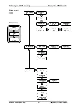
Страница 24: ...fter Taste Fan key Ein Aus Taste On Off key Tasten zur Menüführung Keys for the menu control Display Bedienung der LUBING Steuerung Beispiel Bedienfeld LCS 1 Working with LUBING Controller Example Switch panel Ein Aus Taste On Off key Hand Automatik Taste Hand automatic key Staubbinden Taste Air cleaning key Tageszeitschaltuhr Daily timer Bereich Taste Box key Tasten zur Menüführung Keys for the m...

Страница 25: ...ionstasten werden die verschiedenen Funktionen der Anlage zu oder abgeschaltet Sie gelten für den im Display angezeigten Bereich Hinweis Wird eine Funktion mit den Funktionstasten eingeschaltet erscheinen die eingestellten Wer te im Display Mit der OK Taste kann dann in das entsprechende Menü verzweigt werden Mit der EIN AUS Taste wird die Anlage ein oder ausgeschaltet Beachten Diese Taste hat kei...

Страница 26: ...DI Pausenzeit 30 min OK OK Zeitschaltuhr 08 00 19 00 Startzeit 8 00 Uhr Stopzeit 19 00 Uhr OK OK Einweichen Einweichdauer 3 00 Std MODI Anlage spuelen Auf Ab OK MODI OK Einweichen Start mit OK Ventilation Bereich 1 OK OK Ventilator 2 1 28 C Ventilator 1 1 25 C Sonderfunktionen OK OK Betriebsart 1 auto intern OK Uhr stellen 9 12 00 MODI Entlastungszeit 2 sec MODI MODI Betriebsart MODI Sprache deuts...

Страница 27: ...30 min OK OK Zeitschaltuhr 08 00 19 00 Startzeit 8 00 Uhr Stopzeit 19 00 Uhr MODI OK OK Einweichen Bereich Einweichdauer 3 00 Std Spuelen Box 1 6 Auf Ab OK MODI OK Einweichen Start mit OK Sonderfunktionen LUBING Top Klima System Status Anzeige MODI Spuelen Box 7 14 OK LCM 8 Uhrzeit 14 30 37 OK Uhr stellen 9 12 00 MODI Entlastungszeit 2 sec MODI MODI Sprache deutsch MODI Standardwerte Auf Ab OK Dru...

Страница 28: ...ions on or off In the 2 house versions LC 2 LCS 2 this keys are only for the selected area A LED at the key shows if the function is active Note If you switch on a function with a function key the parameter of this function are shown in the display With the OK key you can go into this menu then The ON OFF key switches the system on or off Note This key is no emergency switch You will find the emer...

Страница 29: ...20 sec MODI Breaking time 30 min OK OK Timer 08 00 19 00 Startzeit 8 00 Uhr Stopzeit 19 00 Uhr OK OK House wetting Wetting time 3 00 Std MODI System flushing Up Down OK MODI OK Start wetting Start mit OK Ventilation OK OK Fan step 2 28 C Fan step 1 25 C Special functions OK OK Running mode auto intern OK Adjust time 9 12 00 MODI Release time 2 sec MODI MODI Running mode MODI Language english MODI ...

Страница 30: ...ying time 1 20 sec MODI Breaking time 1 30 min OK OK Timer 1 08 00 19 00 Startzeit 1 8 00 Uhr Stopzeit 1 19 00 Uhr OK OK House wetting House 1 Wetting time 1 3 00 Std MODI flushing box 1 6 Up Down OK MODI OK Start wetting 1 Start mit OK Special functions Time 14 30 37 MODI flushing box 7 14 OK LCM 8 OK OK Adjust time 9 12 00 MODI Release time 2 sec MODI Language english MODI Standart setting Up Do...

Страница 31: ...ühinter vall gilt sowohl im Hand als auch im Au tomatik Betrieb Staubbinden Im Menüpunkt Staubbinden werden auf dem Display die Sprühzeit und die Pausenzeit des Staubbinden Intervalles angezeigt Mit der OK Taste können die se Werte erreicht und bei Bedarf mit den Tasten geändert werden Before using the Controller After installation the Controller is ready to use If you want to use the function Tim...

Страница 32: ...n angewählt werden Einweichen Im Menüpunkt Einweichen wird mit der OK Taste in das Untermenü Ein weichdauer verzweigt Nachdem die gewünschte Einweichdauer eingestellt und mit der OK Taste gespeichert wur de kann der Einweichvorgang durch er If this function is active the system sprays in the given air cleaning interval if there is no other cooling or humidifying necessary This means the system giv...

Страница 33: ...Temp Hysterese Hier wird die Schalthysterese der Temperatur eingestellt Der Schalt punkt wird um den eingestellten Wert nach oben und nach unten verzögert Feuchte Hyster Hier wird die Schalthysterese the length of wetting and saving it with the OK key you can start wet ting with by pressing the OK key again Now the system sprays with out pause up to the wetting time is over The Status score on the...

Страница 34: ...eige zurück In der Standardanzeige selbst kann mit den Tasten zwischen verschiedenen Informationen gewechselt werden LUBING In der Anzeige erscheint der Banner LUBING Top Klima System Sensoren Es wird die gemessene Temperatur und Luftfeuchte angezeigt Hysterese humid In this menu the switching point of the humidity can be adjusted This means the switching point has a small delay to run the sytem s...

Страница 35: ...atine angeschlossen siehe Anschlusspläne Auch die se Leitungen getrennt verlegen Die Leitungen müssen niederohmig sein 1 5mm 2 Achtung Um Störungen auszuschließen alle Kabel in der Steuerung eng an der Bodenplat te verlegen Achtung Modulplatinen niemals bei einge schalteter Steuerung herausziehen oder ein stecken System sprays The system is in the cooling mode active Air cleaning The system is in ...

Страница 36: ...eparate connected for relais 1 4 5 8 9 10 Eingänge Inputs max 3 Modulplatinen mit je 3 digitalen Eingängen nur für po tentialfreie Schalter und je 1 Temperatureingang 0 10V und je 1 Feuchteeingang 0 10V 15V Versorungsspannung max 3 Modul cards with 3 digital inputs only for switches without potential dry contacts 1 temperatur input 0 10V and 1 humidity input 0 10V 15V supply each Umwelt Enviroment...

Страница 37: ...gen daher sollte zuerst folgendes überprüft werden Richtiger Querschnitt und Dichtigkeit der Saugleitung Zustand der Düse des Überströmventils und des Manometers Es ist sicherzustellen daß alle Absperrventi le in Saug und Druckleitung voll geöffnet sind Informations plunger pump Operation and Maintenance Attention Before operation fill crankcase with engine oil HD SAE 30 or 15 W 40 First oil chang...

Страница 38: ...ufdruck von 1 5 bar erreicht Ein Zulaufdruck bis zu 4 0 bar ist zulässig Druckleitung Wichtig ist daß die Druckleitungen mindestens den gleichen Druchmesser des Pumpeneinlas ses haben Sonst treten Druckverluste auf Au ßerdem muß immer ein Sicherheitsventil instal liert sein das sicherstellt daß der höchstzuläs sige Betriebsdruck nur um max 10 überschrit ten werden kann Bei Fehlen einer solchen Übe...

Страница 39: ... oder Druckventile undicht Fremdkörper in den Ventilen wodurch ein gutes Funktionieren in Frage ge stellt wird Regelungsventilsitz undicht Undichte Dichtungen Düse auswechseln Ventile kontrollieren ggf auswech seln Ventile kontrollieren und reinigen Regelventilsitz kontrollieren und ggf auswechseln Dichtungen kontrollieren ggf er neuern Geräuschzunahme Luftansaugung Saug und oder Druckventilfeder ...

Страница 40: ...orn Suction or delivery valves worn Suction or delivery valves bocked Unloader valve seat worn Worn piston packing Check and replace if necessary Check and replace if necessary Check and clean if necessary Check and replace if necessary Check and replace if necessary Pump noisy Air in suction Broken or weak suction or delivery valve spring Foreign matter in valves Worn bearings Excessive temperatu...

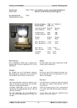
Страница 41: ... 60 140 250 350 Max no of nozzles Min Düsenanzahl bar 20 50 100 140 Min no of nozzles Max Betriebsdruck bar 140 175 100 100 Discharge pressure Leistung kW 0 75 2 2 3 0 5 5 Power Sauganschluß zoll 1 2 1 2 1 2 1 2 Inlet Druckanschluß zoll 3 8 3 8 3 8 3 8 Outlet Gewicht kg 6 7 8 7 20 5 20 5 Weigth Achtung Bei Unterschreiten der minimalen Düsenanzahl kann es zu einer Überhitzung des Pumpen kopfes komm...

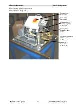
Страница 42: ...Top Climate System Komponenten der Pumpeneinheit Komponents of pump unit Hauptschalter Mainswitch Manometer Manometer Druckregelventil Pressure regulator 7180 7181 Druckschalter Pressure switch 7176 Druckentlastungsventil Unloader valve 7150 Hauptventil Main valve 7162 7163 ...

Страница 43: ...ramikplunger Ceramic pi ston 46976 46841 3 98 Scheibe BUNA N Washer 46730 46730 3 99 Plungerhalter Piston support 46729 46729 3 100 Dichtungshalter Sealing support 46541 46749 3 106 ND Dichtung LP Sealing 43243 43305 3 120 Dichtungshalter Sealing support 46625 46843 3 121 O Ring BUNA N 13976 13978 3 125 HD Dichtung HP Sealing 43245 43307 3 139 Stopfen Einlaß 1 2 Plug 22179 22179 1 162 Stützring Ve...

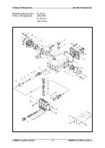
Страница 44: ...Anhang Kolbenpumpe Apendix Plungerpump LUBING Top Klima System 44 LUBING Top Climate System Bildtafel Kolbenpumpe R 230 5 Picture Plungerpump 2R 230 5 R 310 12 2R 310 12 ...

Страница 45: ...ve Pin Valve support O ring Srew Valve Sealing Pump housing Oil Screw Cover Pistom screw O ring Tension ring Washer Piston Cranc shaft Parallel key Sealing Housing Pleuel Pleuel Washer Screw O ring Oil Screw Screw Screw Pin Piston support Piston sealing Screw Cover Distance ring Sealing ring O ring Bearing Mounting support Piston shaft Washer Screw O ring Sealing HP Sealing Sealing Sealing Restop ...

Страница 46: ...st von LUBING auf einen oberen Schaltpunkt von ca 25 bar eingestellt Wird dieser Druck nach Anlauf der Pumpe in der vorgegebenen Wartezeit nicht erreicht schaltet sich die Pumpe automatisch ab Adjusting instructions for pressure switch The pressure switch is adjusted by LUBING to an upper switch point of 25 bar 330 psi If the pressure doesn t reach this switch point in the given waiting time the p...

Страница 47: ...ning the servo valve completely it needs 0 5 bar pressure difference Stopfen Der Stopfen wird zum Verschließen einzelner Düsenaufnahmen verwendet wenn im Bereich der Sprühdüse kein Freiraum vorhanden ist Plug The plug is used for the blocking of single noz zle connectors when not enough space is avail able for free fogging Düsen Die Hochdruckdüsen sorgen bei Drücken ober halb von 50 bar für eine e...

Страница 48: ...Anhang Anschlußpläne Apendix Clamping plans LUBING Top Klima System 48 LUBING Top Climate System Schaltplan Leistungsschaltkasten für Standard Version Clamping plan clamping box for standard version ...

Страница 49: ...Anhang Anschlußpläne Apendix Clamping plans LUBING Top Klima System 49 LUBING Top Climate System Schaltplan Leistungsschaltkasten für Mehrabteilanlagen Clamping plan clamping box for multi houses ...

Страница 50: ...3 Druckentlastung Pressure release S4 Alarm Alarm Ausgänge Outputs LC 2 S1 Hauptventil Mainvalve S2 Pumpe Pump S3 Druckentlastung 1 Pressure release 1 S4 Druckentlastung 2 Pressure release 2 S5 Ventil 1 Valve 1 S6 Ventil 2 Valve 2 S7 Alarm Alarm Ausgänge Outputs LCS 2 S1 Hauptventil Mainvalve S2 Pumpe Pump S3 Druckentlastung 1 Pressure release 1 S4 Druckentlastung 2 Pressure release 2 S5 Ventil 1 ...

Страница 51: ...limatecomputer IN 2 Klimarechner Haus 2 Climatecomp House2 IN 1 Druckschalter schwarz black IN 1 Druckschalter braun brown 10 30V Pressure switch nur LC 2 LCS 2 LC 2 LCS 2 only nur LCS 1 und LCS 2 LCS 1 and LCS 2 only IN 3 Klimarechner Climatecomputer IN 2 Klimarechner Haus 2 Climatecomp House2 IN 1 Druckschalter schwarz black IN 1 Druckschalter braun brown 10 30 V Pressure switch Eingänge Inputs ...

Страница 52: ...climate computer 8 externer Klimarechner 9 climate computer 9 IN 3 externer Klimarechner 1 climate computer 1 IN 2 externer Klimarechner 2 climate computer 2 IN 1 externer Klimarechner 3 climate computer 3 externer Klimarechner 10 climate computer 10 externer Klimarechner 11 climate computer 11 externer Klimarechner 12 climate computer 12 IN 3 externer Klimarechner 4 climate computer 4 IN 2 extern...

Отзывы: