


Chapter 7 Diagnosis Function
7-13
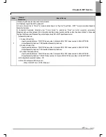
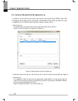
7.4.2 Setting and Connection
All PLCs connected via XGT network are available to connect with each other by remote connection service. XG5000 remote
connection is composed of stage 1 and stage 2 connections as described below.
The followings explains remote 1 and remote 2 connections.
Logical connection via Ethernet module
(remote1)
Network#1
Network#2
Logical connection via Ethernet module
(remote2)
Remote 2
Remote 1
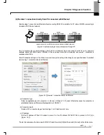
PLC#1
IP: 192.168.91.188
PLC#2
IP: 192.168.91.189
PLC#N
IP: 192.168.91.190
XG5000
Local connection
(RS-232C or USB)
PLC#A
IP: 192.168.91.191
PLC#B
IP: 192.168.91.192
[Figure 7.4.2] Remote connection
[Figure 7.4. 2] shows an example of network system composed of two networks.
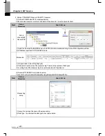
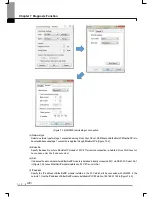
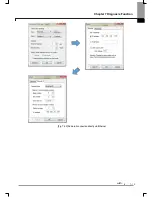
(1) Remote stage 1 connection (If RS-232C cable used)
For remote stage 1 connection, XG5000 shall be in off-line state.
Click [Online] -> [Connection settings]
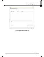
[Figure 7.4.3] XG5000 remote connection option to select
(a) Connection type
It designates the connecting method for local connection. Local connection is applied with RS-232C used as in [Fig.
7.4.3]. Select the port used in PC for a communication port. The case that Ethernet is used for local connection will be
described in the next section. Refer to user’s manual of each communication module for the case with other
connection types.
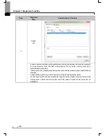
(b) Connection depth
Decide a PLC
c
onnection stage of local, remote stage 1 or 2. Select remote stage 1 here.
Содержание XBL-EIPT
Страница 53: ...Chapter 5 Installation of Software and communication Parameters 5 18 ...
Страница 98: ...Chapter 7 Diagnosis Function 7 11 Figure 7 3 4 FlashArea Log Screen of System Log ...
Страница 106: ...Chapter 7 Diagnosis Function 7 19 Fig 7 4 9 Remote 2 connection directly via Ethernet ...
Страница 119: ...Appendix A 12 A 3 External Dimension Dimension Unit mm XBL EIPT ...