background image

Note

: Use These Instructions for 

Standard


Installations

3.

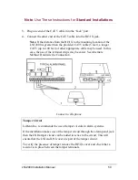
Plug one end of the CAT 5 cable into the “Jack” port.

4.

Connect the other end of the CAT 5 cable into the RJ31X jack.

Note:

 If the distance from the RJ31X to the mounting location of the 

LNI 2000 is greater than the provided CAT 5 cable (5 feet), a longer 
CAT 5 (up to 100 feet) or other appropriate cable may be used. In this 
case, the use of the terminal strips may be easier. See Alternate 
Method: Hardwire the Connection.

Connect to Telephone

Tamper Circuit

LoBenn Inc. recommends the use of tamper circuits in alarm systems. 

If the installation makes use of the tamper circuit through the alarm panel jack 
then the LNI tamper circuit can be added in series to the circuit. This will 
ensure that the LNI and LNI cover are part of the tamper circuit. 

To verify the presence of tamper remove the RJ31X cover and check that a 
resistor is in place between the tamper terminals. 

LNI 2000 Installation Manual

50

Содержание LB200186

Страница 1: ...LOBENN NETWORK INTERFACE 2000 LB200186 Installation Manual April 2010 LB200302 Version 02 03 02 ...

Страница 2: ......

Страница 3: ...p Five Connect To Panel 22 Step Six Complete Installation 23 Step Seven Test The System 25 STANDARD INSTALLATIONS 27 Overview 28 Modes of Operation 29 Materials List 30 Installation Procedure 31 Step One Program the LNI 2000 33 Step Two Mount the LNI 2000 41 Step Three Connect to Power 44 Step Four Connect to Internet 47 Step Five Connect to Telephone 49 Step Six Test The System 55 Removing and Re...

Страница 4: ...Support and Contact Information 70 Certifications and Approvals 71 Compatible LoBenn Network Server LNS Data Formats 75 Glossary of Terms 76 Parts Numbers and Descriptions 82 ...

Страница 5: ... serious property damage Cautions Cautions alert you to practices that may damage equipment or software You will see cautions in the following format CAUTION Movement contact with water accidental contact with other live power sources and accidental disconnection of he LNI 2000 after installation could cause serious damage or malfunction to the unit Notes Notes provide instructions to save time or...

Страница 6: ...Copyright Copyright 2010 LoBenn Inc All rights reserved ...

Страница 7: ...Note Use These Instructions for ULC Installations ULC COMPLIANT INSTALLATIONS LNI 2000 Installation Manual 7 ...

Страница 8: ...ent The installation instructions contained in this manual are intended to assist an installer with the portion of the fire alarm system specific to LoBenn and the LNI 2000 and is not intended to cover the installation instructions of a complete fire alarm system For installation instructions for the other components of an CAN ULC S559 04 and CAN ULC S304 06 listed fire alarm system refer to the i...

Страница 9: ...Note Use These Instructions for ULC Installations 1 Scope of this Installation Manual and Functionality LNI 2000 Installation Manual 9 ...

Страница 10: ...hat use compatible data formats see Compatible LoBenn Network Server LNS Data Formats ULC listed enclosure such as the GE MFC A Accessory Enclosure installed with ULC listed mounting plate and ULC listed 12V DC voltage regulator Shall use the GE 24DC12 compatible by voltage range 21 to 26VDc ULC listed conduit between alarm panel and enclosure containing the LNI 2000 with appropriate cabling in pl...

Страница 11: ...products include but are not limited to A hubs B routers C network interface devices D third party communications service providers E digital subscriber line DSL modems and F cable modems Specifications The table below lists the specifications for the 10 Mbps 10BaseT cable Parameter RJ 45 Cable specification Category 3 or Category 5 UTP with 22 to 24 AWG Maximum segment length 100 m 328 ft for 10B...

Страница 12: ...tal shorts Installation Poster Documentation Card listing web address of all required documentation Not included Two 2 metal screws for mounting the LNI 2000 Minimum length 1 25 inches Recommended length 1 5 inches Additional patch or alarm cabling Tools required for installation Small slotted screwdriver for terminal strip Phillips 1 and 2 screwdriver Tie wraps cable ties LNI 2000 Installation Ma...

Страница 13: ...out removing the terminal strip cover see Removing and Replacing the Terminal Strip Cover on page 57 4 Thread a tie down through the loop inside the terminal strip 2 Mounting the LNI 2000 LNI 2000 Installation Manual WARNING A mounting screw coming in contact with a live electrical wire could result in serious injury or death cause significant property damage and or bring about a circumstance that...

Страница 14: ...ire alarm panel typically 24 Vdc or a ULC listed UPS Uninterruptible Power Supply 1 Make wiring connections as shown in the wiring diagram on the next page 2 For ease of installation connect the 20K resistor between pins 4 and 13 now This resistor is required to establish a tamper circuit For more information see Step Five Connect To Panel on page 22 This resistor may be pre installed Note The add...

Страница 15: ...Note Use These Instructions for ULC Installations 3 Connect to Power CAN ULC S559 04 compliant installation LNI 2000 Installation Manual 15 ...

Страница 16: ...o the Power port on the front of the LNI 2000 1 Connect the LNI 2000 to a PC through the Local port 2 Open a web browser Type 172 21 32 43 into the browser address bar This IP address is shown on the LNI 2000 label on the underside of the LNI 2000 An initial password screen will display 3 Enter the UserName admin and the Password admin 4 The LoBenn LNI Configuration screen will display LNI 2000 In...

Страница 17: ...amper circuit between the panel dialer and the LNI The Tip Ring wires are shorted to the T1 R1 leads respectively when the dialer is on hook 6 To change the LNI 2000 password click on Change Password on the upper right hand corner of the LoBenn LNI Configuration screen Note For security reasons LoBenn Inc recommends changing the password after the LNI has been configured 7 The Change LNI Login Pas...

Страница 18: ... set the configurations on a legacy LNI 2000 with an unknown pass word type 172 21 32 43 factoryreset html into the address bar of a web browser once the LNI 2000 is connected to your PC 2 A Factory Reset LoBenn LNI Configuration screen will display Select Yes and click Submit LNI 2000 Installation Manual 18 ...

Страница 19: ...172 21 32 43 and proceed as described in Points 1 through 7 of this Step to re configure the LNI 2000 to your new settings as specified on the work or der Note After resetting to the factory defaults the UserName and Password are both admin 4 Disconnect cables when the programming is complete LNI 2000 Installation Manual 19 ...

Страница 20: ...monitoring centre Note If the distance from the mounting location of the LNI 2000 to the network router is greater than the provided CAT 5 cable 6 feet a longer CAT 5 cable up to 100 metres 328 feet may be used 1 Connect the LNI 2000 to the router using the LNI 2000 Internet port Do not connect to the router s Internet port 2 Once the cable is connected verify that the LED on the Internet port and...

Страница 21: ... a secondary communications path subject to the following A Low Risk and Medium Risk shall use a dialer as a minimum B High Risk shall use cellular control channel or long range radio as a minimum and C Very High Risk shall be equipped with 24h standby power ULC CAN ULC S304 06 11 4 2 9 and 11 4 3 3 Note To be ULC CAN ULC S S304 06 compatible the Internet Service Provider ISP providing service mus...

Страница 22: ...ng the Dialer 1 jack on the alarm panel and the Panel port on the LNI 2000 2 Once the cable is connected verify that the IP Monitoring LED is lit Note The prior installation of a 20K resistor between terminals 4 and 13 in the LNI 2000 terminal strip establishes a tamper circuit for panels with line seizure capability This capability is necessary for ULC approval 5 Connect to Panel LNI 2000 Install...

Страница 23: ...wrap as specified in the relevant UL specifications 4 Replace terminal strip cover 5 To prevent easy removal or accidental disconnection of the Ethernet cable wrap another tie wrap around it and the already secured power and tele phone cables 6 Secure cover on UL listed enclosure 6 Securing Terminal Strip Cables LNI 2000 Installation Manual 23 CAUTION The terminal strip cover must be raised and lo...

Страница 24: ...ort 2 Wrap this cable tie around all the cables gently directing them towards the port of the enclosure 7 Securing Outside or Port Connections Note The cable ties should be tightened and trimmed before closing the enclosure They are shown loose and untrimmed in both these illustrations for clarity Note LoBenn recommends that the LNI 2000 be wall mounted LoBenn also recommends that there be a cable...

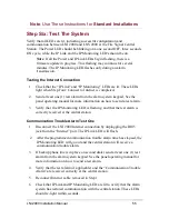
Страница 25: ...arm system keypad See the panel operating manual for more information on how to send a test alarm 3 Verify that the IP Monitoring LED is flashing and that the test alarm is correctly received at the central station Communication Trouble Alarm Test One 1 Disconnect the LNI 2000 Internet connection by unplugging the RJ45 jack from the Internet port The IP Link LED will flash and the IP Monitoring LE...

Страница 26: ... the Panel port 2 After the programmed communication trouble alarm time has elapsed the IP Monitoring LED will stay on and the central station will receive a communication trouble alarm Note To be ULC compliant this CTAT must not be longer than 90 seconds LoBenn recommends using a setting of 90 seconds 3 Verify that the test alarm if applicable and the Communication Trouble Alarm are received corr...

Страница 27: ...Note Use These Instructions for Standard Installations STANDARD INSTALLATIONS LNI 2000 Installation Manual 27 ...

Страница 28: ...ld of High Speed Internet The LoBenn system immediately increases the base level of service by allowing any current dial up alarm installation to be inexpensively upgraded to a fully monitored leased or supervised line level of service The service increase is without the associated line costs and uses or sometimes replaces existing data communication links The installation instructions contained i...

Страница 29: ...en if an alarm is being transmitted 8 LNI 2000 Standard Installation Normal Operations When any part of Internet mode fails relays within the LNI 2000 bring the alarm panel back into the transmission loop as shown below and as would be the case in a phone only alarm system This allows the alarm panel to seize the conventional phone line if an alarm needs to be sent 9 LNI 2000 Standard Installation...

Страница 30: ...only Installation poster Documentation Card listing web address of all required documentation Tools required for installation Slotted screwdriver Phillips 1 and 2 screwdriver Tie wraps cable ties Not included Two 2 6 screws for mounting the LNI 2000 Minimum length 1 25 inches Recommended length 1 5 inches Additional patch or alarm cabling LNI 2000 Installation Manual 30 ...

Страница 31: ...g and fail safe features are noted in the Notes column Standard Recommended Installation Notes LNI 2000 connected to Internet via switch router or high speed modem LNI 2000 connected to telephone voice line LNI 2000 power adapter plugged into UPS and Customer switch router or high speed modem plugged into UPS Full coverage with back up voice line alarm signaling if Internet fails Full protection f...

Страница 32: ...nection The system will fail over to alarm panel voice line if present If no voice line is present alarms cannot be sent Customer modem and switch or router plugged into wall outlet Household power fails The LNI will fail over to alarm panel voice line if present If no voice line is present alarms cannot be sent VoIP installed voice line not connected Power to LNI 2000 fails LNI 2000 will lose Int...

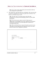
Страница 33: ...ptop configured to obtain IP addresses automatically information from the LNI Pre Installation Site Survey and a web browser 1 Connect the LNI 2000 to your PC with a CAT 5 RJ45 Ethernet cable from the programming port labeled Local to an Ethernet port on your PC Note Your PC should be configured to obtain an IP address automatically DHCP client 2 Power the LNI 2000 by plugging a 12V DC adapter int...

Страница 34: ...address is shown on the LNI 2000 label on the underside of the LNI 2000 An initial password screen will display 4 Enter the UserName admin and the Password admin 5 The LoBenn LNI Configuration screen will display 6 Configure the LNI 2000 by entering the values specified by the work order into appropriate boxes on LoBenn LNI Configuration screen LNI 2000 Installation Manual 34 ...

Страница 35: ...dividual dealer by the monitoring center The code can be any 0 to 6 digits or letters or any combination of 6 digits and letters The dealer code identifies the security company responsible for the security account and allows for targeted upgrades of specific LNI This dealer code should also be reported to the appropriate personnel E Communication trouble alarm time CTAT Minimum and maximum values ...

Страница 36: ...empts to connect are made in order using each address provided The LNI will use the CTAT value before trying each address in sequence Fall back to the PSTN line will only occur after CTAT is exceeded and no connection can be made to a backup LNS or CTAT is not exceeded but the alarm panel is attempting to send an alarm If at that moment a connection cannot be established the LNI will default to th...

Страница 37: ...choose a new password for each LNI 2000 programmed or you may use the same password for every LNI 2000 programmed Note For security reasons there is no reset of this password LoBenn Inc is not responsible for any loss damage or inconvenience resulting from misplacing mis communicating or otherwise not recording this password Note This User ID and the new password should be specified on the work or...

Страница 38: ... on a legacy LNI 2000 with an unknown pass word type 172 21 32 43 factoryreset html into the address bar of a web browser once the LNI 2000 is connected to your PC 7 A Factory Reset LoBenn LNI Configuration screen will display Select Yes and click Submit LNI 2000 Installation Manual 38 ...

Страница 39: ...etting to the factory defaults the UserName and Password are both admin 9 Disconnect cables when programming is complete The LNI 2000 is now ready for repackaging and installation on the customer premises Note If all three LEDs Power IP Link and IP Monitoring begin flashing there is a firmware update in progress Do not disconnect any wiring or power down until the update is complete and the LEDs h...

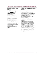
Страница 40: ...configuration of the LNI 2000 Alarm Panel Programming May Be Required Alarm panel ID This number may have to be re programmed on the alarm panel if it has been changed as a part of this installation See the LNI Pre Installation Site Survey for more information Alarm center receiver phone number This number may have to be re programmed on the alarm panel if has been changed as a part of this instal...

Страница 41: ...uter closest to the modem2 It will not be moved or otherwise disturbed There will be no accidental disconnection 1 Some DSL and cable modems are internet sharing devices and act as both a modem and a router If the modem is also a router you can connect the LNI directly to the modem 2 Connecting directly to the high speed modem or a port on a router closest to the modem reduces the number of points...

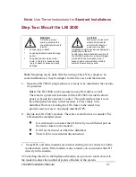
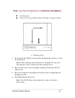
Страница 42: ...te If wall mounting ensure that there are no hidden live electrical wires that may come in contact with the mounting screws 2 Place the first screw but do not tighten completely Ensure that the LNI 2000 is level 3 Place the second screw and tighten by hand to avoid over tightening and damaging the LNI 4 Finish tightening the first screw Note The LNI 2000 may also be placed in a secure location on ...

Страница 43: ...allations Note LoBenn recommends that the LNI 2000 be wall mounted and that there be a cable 4 strap placed using a 6 inch screw within nine 9 inches of the LNI supporting all cables and wires if conduit is not used LNI 2000 Installation Manual 43 ...

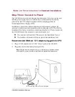
Страница 44: ...gh a UPS The LNI Pre Installation Site Survey should have determined whether a UPS was in place for the LNI 2000 and or the customer s router and modem or if The customer will install a UPS s prior to the Installation Visit or The installer will install a UPS s as part of the Installation Visit Recommended Method 12 V adapter plugged into UPS 1 Plug 12V DC adapter into 12 V DC Power port on the LN...

Страница 45: ...e Removing and Replacing the Terminal Strip Cover on page 57 and Removing the Knockout on page 58 1 After having inserted the tie wrap through the tie wrap anchor thread a length of electrical wiring through the knockout and connect it to the posit ive and negative 12V DC terminals on the LNI 2000 terminal strip Note Use 2 conductor wire not less than 22 AWG and not more than 16 AWG 2 Ensuring pro...

Страница 46: ... wrap before replacing the terminal strip cover 4 Ensure that the power connection is secure from accidental contact with other live power sources and accidental disconnection 1 If there will be no other connections made on the terminal strip replace the terminal strip cover See Removing and Replacing the Terminal Strip Cover on page 57 LNI 2000 Installation Manual 46 ...

Страница 47: ... Router and Network in Place Port Available 1 Using the provided CAT 5 cable plug one end s RJ45 connector into the LNI 2000 at the Internet port 2 Plug the other end s RJ45 connector into a port on the customer s router Note Do not plug into the router s Internet port Note If the distance from the mounting location of the LNI 2000 to the network router is greater than the provided CAT 5 cable 5 f...

Страница 48: ...rts Available If a LAN exists but there are no ports available on its router a switch must be installed to extend the router before installation of the LNI 2000 The LNI Pre Installation Site Survey should have determined whether 1 The customer will install a switch prior to Installation Visit or 2 The installer will install a switch in consultation with the customer as part of the Installation Vis...

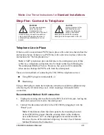
Страница 49: ...hile ensuring a firm and reliable connection Recommended Method RJ45 connection 1 Unplug the existing alarm cable from the RJ31X CA38A jack leaving the other end connected wired to the alarm panel 2 Connect the disconnected cable to the LNI 2000 by plugging it into the Panel port Note If the distance from the alarm panel to the mounting location of the LNI 2000 is greater than the existing alarm c...

Страница 50: ... case the use of the terminal strips may be easier See Alternate Method Hardwire the Connection Connect to Telephone Tamper Circuit LoBenn Inc recommends the use of tamper circuits in alarm systems If the installation makes use of the tamper circuit through the alarm panel jack then the LNI tamper circuit can be added in series to the circuit This will ensure that the LNI and LNI cover are part of...

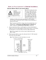
Страница 51: ...arm Panel section of terminal strip on the LNI 2000 Connecting R1 to R1 T1 to T1 R to R T to T and the Tamper terminals to Tamper terminals Note If the distance from the alarm panel to the mounting location of the LNI 2000 is greater than the existing alarm cable fashion a new cable from regular 2 pair quad wire 3 Next thread one end of regular 2 pair quad through the knockout and con nect it to t...

Страница 52: ... this upgrade installation Include a tamper circuit in the upgraded system by connecting a 20K resistor between terminal numbers 4 and 13 on the LNI 2000 terminal strip See Step Two Connect To Power on page 14 of the ULC Compliant Installation section of this manual No Telephone Line There may be no PSTN line or RJ31X in place at the customer s premises for example in a newly built VoIP only home ...

Страница 53: ...t R1 to R1 T1 to T1 R to R T to T and the Tamper terminals to Tamper terminals The maximum gauge for the wire is 16 AWG and the minimum is 22 AWG Note Before starting Option B remove the terminal strip cover and knockout To remove the terminal strip cover and knockout without damaging the tamper switch see Removing and Replacing the Terminal Strip Cover on page 57 and Removing the Knockout on page...

Страница 54: ...tructions for Standard Installations Once tamper circuit has been enabled test the tamper alarm by removing the LNI 2000 terminal strip cover and verifying that a tamper alarm is generated LNI 2000 Installation Manual 54 ...

Страница 55: ...w to send a test alarm 3 Verify that the IP Monitoring LED is flashing and that the test alarm is correctly received at the central station Communication Trouble Alarm Test One 1 Disconnect the LNI 2000 Internet connection by unplugging the RJ45 jack from the Internet port The IP Link LED will flash 2 After the programmed communication trouble alarm time has elapsed the IP Monitoring LED will go o...

Страница 56: ...rrectly at the central station 4 Reconnect the alarm cable removed in Step 1 5 Verify that the Link and IP Monitoring LEDs are still on and that the central station has re established connection and received a restoration alarm Note The programmed Communication Trouble Alarm Time CTAT may be too long for a convenient testing of this capability ULC installations must not exceed a maximum CTAT of 90...

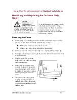
Страница 57: ...htly lifting straight up 2 Pull the terminal strip cover straight back to free it from the slot at the front of the LNI 2000 3 When it is free lift it off the body of the LNI 2000 revealing the terminal strips 4 Notice that the terminal strip cover is shaped to depress and close the tamper switch when it is in place Use extreme caution when replacing the terminal cover 5 Thread a tie wrap through ...

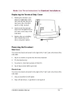
Страница 58: ...ding the terminal strip cover down and gently tighten Removing the Knockout Metal Case To remove the knockout located to the right of the Jack port at the front of the LNI 2000 1 Insert a screwdriver tip into the slot in the knockout 2 Pry the knockout up 3 Use pliers to twist the knockout off the LNI 4 Insert the provided rubber grommet Plastic Case To remove the knockout located to the right of ...

Страница 59: ...For All Installations FOR ALL INSTALLATIONS LoBenn Network Interface 2000 Installation Manual 59 ...

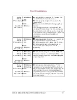
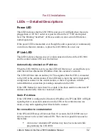
Страница 60: ...of 3 seconds on 1 second off indicates normal operation Unit is acquiring an IP address from the router Unit is not connected to the alarm central station In some cases acquiring an IP address may occur so quickly that the LED does not flash Power IP Link IP Monitoring Local Port Internet Port On Off On Off Active Boot phase Unit is powered The firmware is initializing the hardware Remains in this...

Страница 61: ...on 1 second off indicates normal operation Unit has acquired an IP address from the router Unit has established an IP connection to the alarm central station Relays are set to IP monitoring Power IP Link IP Monitoring Local Port Internet Port Flashing Flashing Flashing Off Active Unit is downloading a new version of firmware This process may take several minutes Please wait until the flashing stop...

Страница 62: ...rn on and stay lit This signifies that the LNI is connected to the LNS at the central station If the LED fails to light the unit is improperly configured to connect to the central station or there is a problem with the network Internet connection preventing connection to the LNS If the LED flashes for more than 30 seconds it has been unable to obtain an IP address automatically from the customer s...

Страница 63: ...the Internet This LED will light after the connection to the LNS is established see IP Link LED above and relays in the LNI 2000 are set for Internet alarm monitoring This LED will flash every time the panel sends Alarm Restore Alarm Port LEDs The Local and Internet ports have paired LEDs one pair for each port that indicate Ethernet transmission activity These LEDs will be on when there is a phys...

Страница 64: ...es The Connection Properties window will open Change Connection Settings 1 On the General tab if you have selected a local area connection or the Net working tab if you have selected a Dial up or other connection click In ternet Protocol TCP IP then click the Properties button The Internet Protocol TCP IP Properties window will open 2 Select Obtain and IP address automatically and Obtain DNS serve...

Страница 65: ...ter The alarm system s Internet connection must be made through a combined modem router or router via the LNI 2000 Installation cannot be completed without a high speed modem router or a router The LNI Pre Installation Site Survey should have determined whether or not a router was required and when the router would be installed either prior to or during the Installation Visit LoBenn Inc recommends...

Страница 66: ... the router the cable must NOT be connected to the WAN or Internet port Should the LED still fail to light try another cable there may be a fault in the cable There is a small chance that the LED is defective To determine this continue the installation procedure and configure the LNI with the IP address of the monitoring center If the IP Link LED fails to light as well then the unit is probably de...

Страница 67: ... Ensure that the router is powered In very rare cases it is possible that the CAT5 cable is faulty Replace with another cable 4 If the LED is lit the customer s LAN is not allowing the LNI to obtain an IP address automatically A static address must be used To configure the LNI 2000 with a static address 5 Obtain a static IP address from the customer Set up the LNI 2000 on the customer s network wi...

Страница 68: ...er to verify these values It is also possible that the monitoring center LNS is not currently accepting connections from an LNI This is rare and temporary This should resolve itself within the Communication Trouble Alarm Time set in Step One Program the LNI 2000 If it does not the LNI will switch to the secondary LNS if one was configured While the IP Monitoring LED is off the unit s relays are in...

Страница 69: ...Current 10 VDC to 14 VDC 300 mA Maximum Operating temperature 32 to 120ºF 0 to 49ºC Humidity 93 Non condensing IP Connection 10 100 BaseT Ethernet Cable Category 3 or better 10 baseT Category 5 or better 100 BaseT 100 m 328ft maximum Wire gauge for terminal strip Minimum 22 AWG Maximum 16 AWG Recommended wire gauge for terminal strip 22 AWG LoBenn Network Interface 2000 Installation Manual 69 ...

Страница 70: ... when installing the LoBenn LNI 2000 LoBenn Inc global support can be reached in North America at Phone 1 866 599 1415 World Wide Web http www lobenninc com support php General Contact Information LoBenn Inc 105 Willowlea Road Ottawa ON K0A 1L0 Phone 613 599 1415 Toll free 866 599 1415 Fax 613 599 2091 General Information info lobenninc com Sales sales lobenninc com Web www lobenninc com LoBenn Ne...

Страница 71: ...harmful interference to radio communications However there is no guarantee that interference will not occur in a particular installation If this equipment does cause harmful interference to radio or television reception which can be determined by turning the equipment off and on the user is encouraged to try to correct the interference by one or more of the following measures Reorient or relocate ...

Страница 72: ... and UL 1610 This equipment is UL listed to UL 864 and UL 1610 Communications Basic Line Security This product meets the requirement for communication basic line security level Other UL Compliance Requirements Receiver To be UL 864 and UL 1610 compatible the system must be used with a listed receiver Network and Domain Access To be UL 1610 compatible network access and domain access policies shall...

Страница 73: ...1 03 and or CAN ULC S304 06 this product MUST be installed in a ULC certified Signal Receiving Centre that provides this product with standby supply from both of the following sources 1 A standby generator that complies with the applicable ULC requirements associated with a Signal Receiving Centre AND 2 an uninterruptible power supply UPS that is capable of maintaining operation for 4 hours and th...

Страница 74: ...ust not load other Linux based applications on the LNS that may breach security CAN ULC S304 06 11 4 2 7 Backup Power To be ULC CAN ULC S559 04 and CAN ULC S304 06 compatible power for network equipment as hubs switchers routers servers modems etc shall be backed up or powered by a Listed UPS stand by battery or the control unit capable of facilitating 24 hour standby compliant with Clauses 16 1 2...

Страница 75: ...ch perform communications functions only these products or components shall comply with the applicable requirements specified in UL 864 and UL 1610 Information Technology Equipment Safety Part 1 General Requirements Such products include but are not limited to A hubs B routers C network interface devices D third party communication service providers E digital subscriber line DSL modems and F cable...

Страница 76: ...SA 22 2 TUV EN60950 1 European Union The LNI complies with TBR 21 EU 55022 1998 Class B EU 55024 1998 EU 60950 1992 RoHS This equipment complies with the Restriction of Hazardous Substances RoHS directive 2002 95 EC LoBenn Network Interface 2000 Installation Manual 76 ...

Страница 77: ...Ia2 Radionics BFSK SIA Bell 103 110 300 baud Yes Yes Yes Table 3 Compatible Radionics and SIA Bell Formats Pulse DTMF 3 1 3 1 Checksum 4 2 Contact ID ADEMCO High Speed ADEMCO 4 2 Express No No No Yes Yes Yes Table 4 Compatible Pulse and DTMF Formats LoBenn Network Interface 2000 Installation Manual 77 ...

Страница 78: ... wall mounted telephone jack containing simple screw terminals USOC color coded for compatibility with standard telephone systems The CA38A is installed in the line between the CO and the house phones allowing a security system to have separate connections to the inside phones and the CO line Identified in the United States as RJ31X Cable Modem Modem for high speed Internet access over a cable TV ...

Страница 79: ...ols data formatting or organizational structures When networks are divided into subnets gateways are often used to isolate one subnet from another to control network traffic On TCP IP networks each network device is often configured with the IP address of the nearest gateway If there are no gateways on the network the IP address of your computer is typically used Internet The Internet is a global ...

Страница 80: ...er devices such as modems routers and printers are geographically close together typically in the same building LNI LoBenn Network Interface LNS LoBenn Network Server Modem Modulator demodulator A modem is a device or program that enables a computer to transmit digital data through the World Wide Web to another computer The modem converts the data from the sender into a format that first can be se...

Страница 81: ... as PCs and the LNI 2000 can be set to obtain an IP address automatically usually from a router on the customer s LAN PCs can also be set to get or provide an IP address automatically See DHCP POTS Plain Old Telephone Service also known as PSTN PSTN Public Switched Telephone Network the international telephone system based on copper wires carrying analog voice data Newer telephone networks are bas...

Страница 82: ...rinters A network server is a computer that manages network traffic A database server is a computer system that processes database queries Internet servers store and serve the specially formatted documents viewed by web browsers the addresses for these documents include the IP address of the server LoBenn Network Server stores the monitoring information for a number of individual LNIs When an LNI ...

Страница 83: ...ata in packets using IP rather than by traditional circuit transmissions of the PSTN VoIP is a system of both hardware and software This Internet telephony is gaining in popularity because with free or fixed price Internet access through an ISP it eliminates the need for a separate dedicated voice phone line and provides extremely low cost telephone calls to anywhere in the world Disadvantages to ...

Страница 84: ...ence card to web addresses of all documentation LB200291 Basic Install Kit Basic 12 volt LNI unit 2 CAT5 cables 2 grommets Quick Install poster Quick reference card to web addresses of all documentation LB200022 12 volt DC Power Pak LB200335 24 volt LNI unit LB200337 24 volt LNI unit LB200335 Power Pak LB200336 2 CAT5 cables 2 grommets Quick Install poster LB200336 24 VDC Power Pak LoBenn Network ...

Страница 85: ...For All Installations LoBenn Network Interface 2000 Installation Manual 85 ...

Страница 86: ...Printed in Canada December 2009 LB200302 Version 02 03 02 ...

Отзывы: