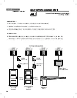
WIRELESS INSTALLATION TIPS
Signals Through Construction Materials
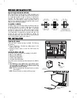
When installing any wireless system, certain limitations must
be considered. Low power wireless UHF transmitter signals will
not broadcast equally through all types of construction
materials. The AM/II contains a receiver that should allow
reception of the transmitters in almost all locations. Refer to
figure showing approximate signal strength that will occur with
different types of building materials.
Transmitters in Vehicles
The radio range of a transmitter will also be affected when the
transmitter is located in a vehicle. Depending on the location
of the transmitter (on the visor, on the dash, in the center
console) the range will vary. Most of the signal strength
changes are related to the amount of metal in close proximity
to the transmitter. If a transmitter is clipped to the top of the
driver’s sun visor, with the visor flipped up, placing the
transmitter between the metal roof and the metal reinforced
visor, the transmitters range will be reduced.
PRE-INSTALLATION
Unpacking the System
The basic AM/II system package includes the following
accessories:
✶
Plug-in Transformer. Provides low voltage power to the
access control panel.
✶
Mounting Screws. Used to mount the AM/II inside the
cabinet.
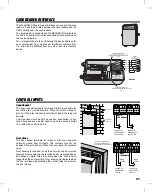
Installing the Memory Module
Four sizes of memory modules are available for the AM/II:
✶
SMALL (16K) MEMORY
✶
MEDIUM (64K) MEMORY
✶
LARGE (128K) MEMORY
✶
X-LARGE (256K) MEMORY
One of the memory modules must be installed for the AM/II to
function.
✘
CAUTION! Be sure the AM/II is disconnected from power
or that the AM/II’s POWER switch is off before removing
of replacing the memory module.
STEP 1 With the system power off, plug the memory module
into the AM/II.
STEP 2 Secure the memory module with two screws.
90% - 100%
OF FULL POWER
65% - 95%
OF FULL POWER
10% - 70%
OF FULL POWER
WALLBOARD AND
WOOD STUDS
CONCRETE WITH STEEL
REINFORCEMENT OR
METAL LATH AND PLASTER
LIGHT CONCRETE
OR BRICK
AM/II UNIT WITH MEMORY INSTALLED
PLUG-IN
TRANSFORMER
CASE MOUNTING
SCREWS
RADIO
DECODE
ACCESS GRANTED
READER KEYPAD
ACCESS OUT DATA
NETWORK DATA
ACCESS A
ACCESS B
ACCESS C
OBSTACLE
MAGIC WAND
ACCESS D
B
O
1
O
1
O
1
B
O
1
N.O. COM. N.C.
N.O. COM. N.C. N.O. COM. N.C. N.O. COM. N.C.
EARTH
GROUND
ACCESS OUT
KEYPAD IN
CHANNEL A
CHANNEL B
CHANNEL C
CHANNEL D
READER IN
14 - 24 VAC
12 - 35 VDC
AC POWER
INPUT
DC POWER
INPUT
NETWORK
OFF
ON
POWER
RESET
DISPLAY
CONTRAST
MEMORY EXPANSION CARD
MEDIUM (64 K)
SMALL (16 K)
LARGE (128 K)
X-LARGE (256 K)
WARNING
TURN THE POWER SWITCH OFF BEFORE INSTALLING OR
REMOVING THIS MEMORY EXPANSION CARD
SEVERE
ELECTRICAL
DAMAGE
INSTALL MEMORY
MODULE
21

