


Service Training
Section
2.6
Page
44
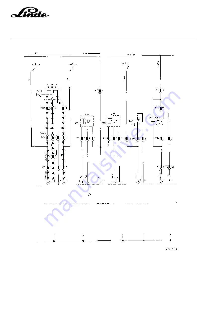
On single-pedal model trucks, the directional contactors are controlled via travel direction switch 1S13, which
is located on the steering column.
This travel direction switch is connected to the electronic traction control unit via 4-pin flat connector 1X9.
The black/blue cable coming from the electronic traction control unit (1X13:7) is connected to terminal 2 of
4-pin connector 1X9.
The directional switch is used to apply battery negative to 1X13:8 when driving forward or to 1X13:22 when
reversing. This battery negative signal then takes over control of the directional transistors in the electronic
traction control unit.
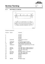
2.6.6.4
SINGLE PEDAL MODELS
Содержание 336 Series
Страница 2: ......
Страница 8: ...ServiceTraining ...
Страница 12: ...ServiceTraining Section 2 1 Page 4 ...
Страница 14: ...ServiceTraining Section 2 1 Page 6 2 1 4 TRACTIONMOTORDISASSEMBLY ...
Страница 19: ...ServiceTraining Section 2 2 Page 3 ...
Страница 21: ...ServiceTraining Section 2 2 Page 5 ...
Страница 27: ...ServiceTraining Section 2 2 Page 11 ...
Страница 28: ...ServiceTraining Section 2 2 Page 12 ...
Страница 33: ...ServiceTraining Section 2 4 Page 1 2 4 STEERING SYSTEM ...
Страница 35: ...ServiceTraining Section 2 4 Page 3 ...
Страница 37: ...ServiceTraining Section 2 4 Page 5 ...
Страница 39: ...ServiceTraining Section 2 4 Page 7 ...
Страница 41: ...ServiceTraining Section 2 4 Page 9 ...
Страница 45: ...ServiceTraining Section 2 4 Page 13 ...
Страница 47: ...ServiceTraining Section 2 4 Page 15 ...
Страница 53: ...ServiceTraining Section 2 5 Page 5 ...
Страница 54: ...ServiceTraining Section 2 5 Page 6 ...
Страница 69: ...ServiceTraining Section 2 6 Page 15 ...
Страница 70: ...ServiceTraining Section 2 6 Page 16 2 6 2 CONTACTORS 2 6 2 1 DIRECTIONALCONTACTORS Circuit diagram ...
Страница 74: ...ServiceTraining Section 2 6 Page 20 2 6 2 3 CIRCUIT BREAKER CONTACTOR 1K6 Circuit diagram ...
Страница 94: ...ServiceTraining Section 2 6 Page 40 ...
Страница 111: ...ServiceTraining Section 2 6 Page 57 Connector 1X6 1 15 V 2 Output signal 3 ...
Страница 124: ...ServiceTraining Section 2 6 Page 70 2 6 9 LOCATION OF CONNECTORS 2 6 9 1 LOCATION OF CONNECTORS TO SERIES 6 95 ...
Страница 126: ...ServiceTraining Section 2 6 Page 72 2 6 9 2 LOCATION OF CONNECTORS FROM SERIES 7 95 ...
Страница 128: ...ServiceTraining Section 2 6 Page 74 ...
Страница 145: ...Section 2 6 Page 91 ...
Страница 146: ......
Страница 147: ......
Страница 149: ...Section 2 6 Page 93 ...
Страница 150: ......
Страница 153: ...ServiceTraining Section 2 7 Page 3 ...
Страница 157: ...ServiceTraining Section 2 7 Page 7 ...
Страница 158: ...ServiceTraining Section 2 7 Page 8 ...
Страница 163: ...Section 2 9 Page 5 ...
Страница 164: ......
Страница 166: ...ServiceTraining Section 2 10 Page 2 ...
Страница 167: ......