


Service Training
Section
2.6
Page
65
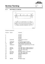
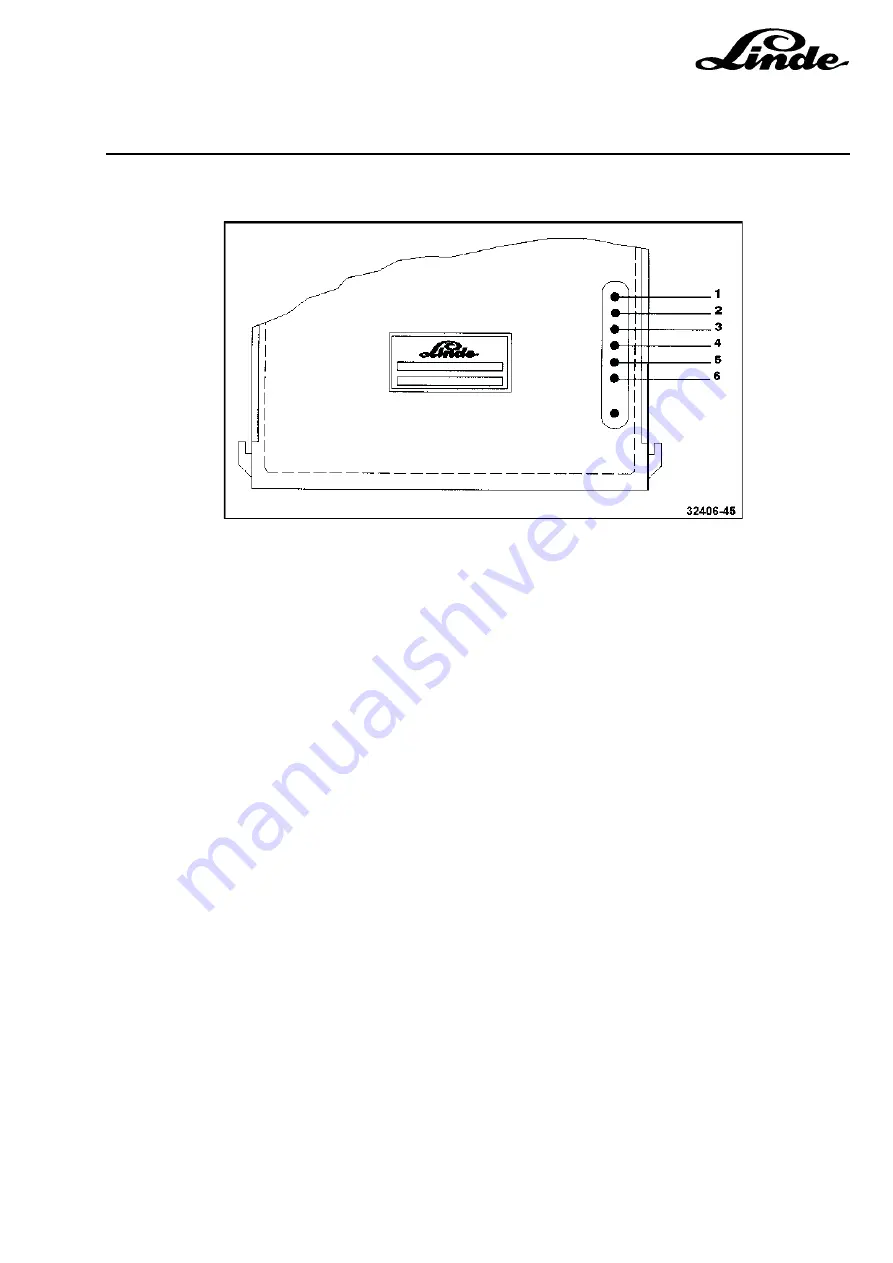
2.6.7.1.5
ADJUSTMENTS
1
Not used
2
Not used
3
Auxiliary hydraulics 1, function 1
4
Auxiliary hydraulics 2, function 2
5
Auxiliary hydraulics 2
6
Not used
LIFTING
The lifting cycle is enabled by distance sensor 2B11. The motor speed is controlled with distance sensor
2B11 on the control valve proportionally to the movement of the spool. The lifting cycle does not need to be
adjusted.
TILTING
The tilting cycle is enabled with distance sensor 2B12. The tilting cycle does not need to be adjusted.
AUXILIARY HYDRAULICS 1
The work cycle is enabled with sensor 2B13. The motor speed is set with potentiometers (3) and (4). With
potentiometer (3) it is possible to adjust the motor speed for function 1 (rotate clockwise, shift to the right,
etc.). With potentiometer (4) it is possible to adjust function 2 (rotate anti-clockwise, shifting to the left). The
setting of the motor speed depends on the type of attachment and it should be taken from the specifications
of the manufacturer of the attachment.
AUXILIARY HYDRAULICS 2
The work cycle is enabled with sensor 2B14. The motor speed is set with potentiometer (5). The setting of
the motor speed depends on the type of attachment and it should be taken from the specifications of the
manufacturer of the attachment.
NOTE:
Use a suitable screwdriver for the adjustment. All adjustments must be performed from outside
through the holes indicated by the illustration. Carry out the adjustment of the motor speed with
the right amount of force. Refit the sealing cap after completion of the adjustment.
Содержание 336 Series
Страница 2: ......
Страница 8: ...ServiceTraining ...
Страница 12: ...ServiceTraining Section 2 1 Page 4 ...
Страница 14: ...ServiceTraining Section 2 1 Page 6 2 1 4 TRACTIONMOTORDISASSEMBLY ...
Страница 19: ...ServiceTraining Section 2 2 Page 3 ...
Страница 21: ...ServiceTraining Section 2 2 Page 5 ...
Страница 27: ...ServiceTraining Section 2 2 Page 11 ...
Страница 28: ...ServiceTraining Section 2 2 Page 12 ...
Страница 33: ...ServiceTraining Section 2 4 Page 1 2 4 STEERING SYSTEM ...
Страница 35: ...ServiceTraining Section 2 4 Page 3 ...
Страница 37: ...ServiceTraining Section 2 4 Page 5 ...
Страница 39: ...ServiceTraining Section 2 4 Page 7 ...
Страница 41: ...ServiceTraining Section 2 4 Page 9 ...
Страница 45: ...ServiceTraining Section 2 4 Page 13 ...
Страница 47: ...ServiceTraining Section 2 4 Page 15 ...
Страница 53: ...ServiceTraining Section 2 5 Page 5 ...
Страница 54: ...ServiceTraining Section 2 5 Page 6 ...
Страница 69: ...ServiceTraining Section 2 6 Page 15 ...
Страница 70: ...ServiceTraining Section 2 6 Page 16 2 6 2 CONTACTORS 2 6 2 1 DIRECTIONALCONTACTORS Circuit diagram ...
Страница 74: ...ServiceTraining Section 2 6 Page 20 2 6 2 3 CIRCUIT BREAKER CONTACTOR 1K6 Circuit diagram ...
Страница 94: ...ServiceTraining Section 2 6 Page 40 ...
Страница 111: ...ServiceTraining Section 2 6 Page 57 Connector 1X6 1 15 V 2 Output signal 3 ...
Страница 124: ...ServiceTraining Section 2 6 Page 70 2 6 9 LOCATION OF CONNECTORS 2 6 9 1 LOCATION OF CONNECTORS TO SERIES 6 95 ...
Страница 126: ...ServiceTraining Section 2 6 Page 72 2 6 9 2 LOCATION OF CONNECTORS FROM SERIES 7 95 ...
Страница 128: ...ServiceTraining Section 2 6 Page 74 ...
Страница 145: ...Section 2 6 Page 91 ...
Страница 146: ......
Страница 147: ......
Страница 149: ...Section 2 6 Page 93 ...
Страница 150: ......
Страница 153: ...ServiceTraining Section 2 7 Page 3 ...
Страница 157: ...ServiceTraining Section 2 7 Page 7 ...
Страница 158: ...ServiceTraining Section 2 7 Page 8 ...
Страница 163: ...Section 2 9 Page 5 ...
Страница 164: ......
Страница 166: ...ServiceTraining Section 2 10 Page 2 ...
Страница 167: ......