


Service Training
Section
2.4
Page
6
2.4.1.3
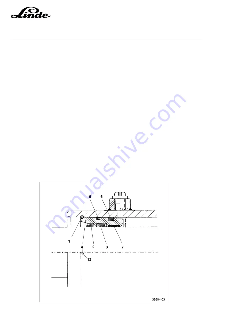
RENEWING THE STEERING CYLINDER SEALS
- Remove the steering axle and steering cylinder.
- Clamp the steering cylinder in a vice.
- Pull the piston rod out as far as possible to one side.
- Press guide bushing approx. 2 to 3 mm into the cylinder housing sung a sleeve.
- Loosen the retaining ring (1) with a drift punch through hole (12) at the cylinder barrel and remove it with
a screwdriver.
- Slide the piston rod in the direction of the removed retaining ring and drive out the guide bushing (4) with
light taps (soft hammer) on the end of the opposite piston rod and guide the opposite piston rod end with
the hand..
- Pull the piston rod out of the cylinder and remove the guide bushing (4) from the piston rod, taking care
not to damage the guide bushing.
- Remove the O-rings (5) and (6), U-cup packing (3), wiper (2) and guide band (7) from the guide bushing
- Install new O-rings, U-cup packing, wiper and guide band, taking care to position the single sealing parts
correctly (see detail 33604-03).
- Remove the sealing ring (11) and guide band (10) from the piston rod and renew them.
- Remove the second retaining ring (1).
- Remove the guide bushing (4) and renew the sealing elements.
- Slightly grease the guide bushing (4) and install it in the cylinder, paying attention to its correct position
(chamfer on the out, side circumference shows out).
- Install the retaining ring (1).
- Carefully insert the piston rod (9) into the cylinder from the opposite end and slide it in as far as possible
through the guide bushing (4), taking care not to damage the sealing lips of the sealing elements.
- Insert the second greased guide bushing (4), slide it in as far as the stop and fasten it with the retaining
ring (1).
Содержание 336 Series
Страница 2: ......
Страница 8: ...ServiceTraining ...
Страница 12: ...ServiceTraining Section 2 1 Page 4 ...
Страница 14: ...ServiceTraining Section 2 1 Page 6 2 1 4 TRACTIONMOTORDISASSEMBLY ...
Страница 19: ...ServiceTraining Section 2 2 Page 3 ...
Страница 21: ...ServiceTraining Section 2 2 Page 5 ...
Страница 27: ...ServiceTraining Section 2 2 Page 11 ...
Страница 28: ...ServiceTraining Section 2 2 Page 12 ...
Страница 33: ...ServiceTraining Section 2 4 Page 1 2 4 STEERING SYSTEM ...
Страница 35: ...ServiceTraining Section 2 4 Page 3 ...
Страница 37: ...ServiceTraining Section 2 4 Page 5 ...
Страница 39: ...ServiceTraining Section 2 4 Page 7 ...
Страница 41: ...ServiceTraining Section 2 4 Page 9 ...
Страница 45: ...ServiceTraining Section 2 4 Page 13 ...
Страница 47: ...ServiceTraining Section 2 4 Page 15 ...
Страница 53: ...ServiceTraining Section 2 5 Page 5 ...
Страница 54: ...ServiceTraining Section 2 5 Page 6 ...
Страница 69: ...ServiceTraining Section 2 6 Page 15 ...
Страница 70: ...ServiceTraining Section 2 6 Page 16 2 6 2 CONTACTORS 2 6 2 1 DIRECTIONALCONTACTORS Circuit diagram ...
Страница 74: ...ServiceTraining Section 2 6 Page 20 2 6 2 3 CIRCUIT BREAKER CONTACTOR 1K6 Circuit diagram ...
Страница 94: ...ServiceTraining Section 2 6 Page 40 ...
Страница 111: ...ServiceTraining Section 2 6 Page 57 Connector 1X6 1 15 V 2 Output signal 3 ...
Страница 124: ...ServiceTraining Section 2 6 Page 70 2 6 9 LOCATION OF CONNECTORS 2 6 9 1 LOCATION OF CONNECTORS TO SERIES 6 95 ...
Страница 126: ...ServiceTraining Section 2 6 Page 72 2 6 9 2 LOCATION OF CONNECTORS FROM SERIES 7 95 ...
Страница 128: ...ServiceTraining Section 2 6 Page 74 ...
Страница 145: ...Section 2 6 Page 91 ...
Страница 146: ......
Страница 147: ......
Страница 149: ...Section 2 6 Page 93 ...
Страница 150: ......
Страница 153: ...ServiceTraining Section 2 7 Page 3 ...
Страница 157: ...ServiceTraining Section 2 7 Page 7 ...
Страница 158: ...ServiceTraining Section 2 7 Page 8 ...
Страница 163: ...Section 2 9 Page 5 ...
Страница 164: ......
Страница 166: ...ServiceTraining Section 2 10 Page 2 ...
Страница 167: ......