


Service Training
Section
2.4
Page
12
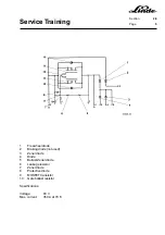
2.4.1.6
INSTALLING THE STEERING CYLINDER AND TRACK ROD LINK
- Insert the track rod links (5) into the steering cylinder (1).
- Coat the pin (14) with MoS
2
grease and press it in (pressing force 5 - 50 kN).
- Secure the pin (14) with a roll pin (13).
- Place the steering cylinder along with the track rod links on the centre axle (9).
- Install the marked bearing brackets (8) correctly and fasten them with screws (7) (torque to 425 Nm).
- Coat the pin (3) with MoS
2
grease and press it into the track rod link (5) and steering knuckle arm with the
roller pin pointing up (pressing force 4 - 38 kN).
NOTE:
When pressing in pin (3), support the steering knuckle arm from below to prevent any damage
to it.
- Secure pin (3) with a roll pin (2).
- Install the hydraulic hoses (10) along with the banjo screws (11) and O-rings (12) on the steering cylinder
(1).
Содержание 336 Series
Страница 2: ......
Страница 8: ...ServiceTraining ...
Страница 12: ...ServiceTraining Section 2 1 Page 4 ...
Страница 14: ...ServiceTraining Section 2 1 Page 6 2 1 4 TRACTIONMOTORDISASSEMBLY ...
Страница 19: ...ServiceTraining Section 2 2 Page 3 ...
Страница 21: ...ServiceTraining Section 2 2 Page 5 ...
Страница 27: ...ServiceTraining Section 2 2 Page 11 ...
Страница 28: ...ServiceTraining Section 2 2 Page 12 ...
Страница 33: ...ServiceTraining Section 2 4 Page 1 2 4 STEERING SYSTEM ...
Страница 35: ...ServiceTraining Section 2 4 Page 3 ...
Страница 37: ...ServiceTraining Section 2 4 Page 5 ...
Страница 39: ...ServiceTraining Section 2 4 Page 7 ...
Страница 41: ...ServiceTraining Section 2 4 Page 9 ...
Страница 45: ...ServiceTraining Section 2 4 Page 13 ...
Страница 47: ...ServiceTraining Section 2 4 Page 15 ...
Страница 53: ...ServiceTraining Section 2 5 Page 5 ...
Страница 54: ...ServiceTraining Section 2 5 Page 6 ...
Страница 69: ...ServiceTraining Section 2 6 Page 15 ...
Страница 70: ...ServiceTraining Section 2 6 Page 16 2 6 2 CONTACTORS 2 6 2 1 DIRECTIONALCONTACTORS Circuit diagram ...
Страница 74: ...ServiceTraining Section 2 6 Page 20 2 6 2 3 CIRCUIT BREAKER CONTACTOR 1K6 Circuit diagram ...
Страница 94: ...ServiceTraining Section 2 6 Page 40 ...
Страница 111: ...ServiceTraining Section 2 6 Page 57 Connector 1X6 1 15 V 2 Output signal 3 ...
Страница 124: ...ServiceTraining Section 2 6 Page 70 2 6 9 LOCATION OF CONNECTORS 2 6 9 1 LOCATION OF CONNECTORS TO SERIES 6 95 ...
Страница 126: ...ServiceTraining Section 2 6 Page 72 2 6 9 2 LOCATION OF CONNECTORS FROM SERIES 7 95 ...
Страница 128: ...ServiceTraining Section 2 6 Page 74 ...
Страница 145: ...Section 2 6 Page 91 ...
Страница 146: ......
Страница 147: ......
Страница 149: ...Section 2 6 Page 93 ...
Страница 150: ......
Страница 153: ...ServiceTraining Section 2 7 Page 3 ...
Страница 157: ...ServiceTraining Section 2 7 Page 7 ...
Страница 158: ...ServiceTraining Section 2 7 Page 8 ...
Страница 163: ...Section 2 9 Page 5 ...
Страница 164: ......
Страница 166: ...ServiceTraining Section 2 10 Page 2 ...
Страница 167: ......