


Service Training
Section
2.4
Page
14
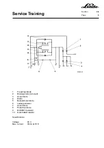
2.4.1.7
INSTALLING THE STEERING AXLE
- Put two rubber axle blocks (10) on the centre axle.
- Install the steering axle (11) with the axle blocks (10) in the counterweight (3) from below, raise it slightly
until the axle blocks contact the counterweight and safely support it.
- Lead both hydraulic hoses through the counterweight into the battery compartment.
- Lead the steering sensor cables into the counterweight.
- Coat the steering fastening screws (8) with Loctite 243.
- Secure the two plates (9) and rubber axle mounts (10) with the screws (8).
- Torque the screws (8) to 195 Nm.
- On trucks without the higher driver’s seat, install the additional weight (4) in the counterweight from below
and safely support it.
- Install the first fastening screw (2) through the hole for the trailer coupling pin.
NOTE:
On trucks from series 10/94, the mounting bolt (2) can be accessed from below at the ballast
weight (4).
- Install the second fastening screw (7) along with the plate (6).
- Tighten both screws.
- Connect the two steering cylinder hose lines to the appropriate pipelines.
- Connect the proximity switch connectors X6 and X7.
- Install the battery.
- Eliminate any air in the steering by operating the steering wheel through 10 complete travel cycles.
- Check the oil level in the oil reservoir and add oil, if necessary.
- Remount the wheels.
- Lower the truck to the ground.
- Torque opposite wheel bolts to 180 Nm.
Содержание 336 Series
Страница 2: ......
Страница 8: ...ServiceTraining ...
Страница 12: ...ServiceTraining Section 2 1 Page 4 ...
Страница 14: ...ServiceTraining Section 2 1 Page 6 2 1 4 TRACTIONMOTORDISASSEMBLY ...
Страница 19: ...ServiceTraining Section 2 2 Page 3 ...
Страница 21: ...ServiceTraining Section 2 2 Page 5 ...
Страница 27: ...ServiceTraining Section 2 2 Page 11 ...
Страница 28: ...ServiceTraining Section 2 2 Page 12 ...
Страница 33: ...ServiceTraining Section 2 4 Page 1 2 4 STEERING SYSTEM ...
Страница 35: ...ServiceTraining Section 2 4 Page 3 ...
Страница 37: ...ServiceTraining Section 2 4 Page 5 ...
Страница 39: ...ServiceTraining Section 2 4 Page 7 ...
Страница 41: ...ServiceTraining Section 2 4 Page 9 ...
Страница 45: ...ServiceTraining Section 2 4 Page 13 ...
Страница 47: ...ServiceTraining Section 2 4 Page 15 ...
Страница 53: ...ServiceTraining Section 2 5 Page 5 ...
Страница 54: ...ServiceTraining Section 2 5 Page 6 ...
Страница 69: ...ServiceTraining Section 2 6 Page 15 ...
Страница 70: ...ServiceTraining Section 2 6 Page 16 2 6 2 CONTACTORS 2 6 2 1 DIRECTIONALCONTACTORS Circuit diagram ...
Страница 74: ...ServiceTraining Section 2 6 Page 20 2 6 2 3 CIRCUIT BREAKER CONTACTOR 1K6 Circuit diagram ...
Страница 94: ...ServiceTraining Section 2 6 Page 40 ...
Страница 111: ...ServiceTraining Section 2 6 Page 57 Connector 1X6 1 15 V 2 Output signal 3 ...
Страница 124: ...ServiceTraining Section 2 6 Page 70 2 6 9 LOCATION OF CONNECTORS 2 6 9 1 LOCATION OF CONNECTORS TO SERIES 6 95 ...
Страница 126: ...ServiceTraining Section 2 6 Page 72 2 6 9 2 LOCATION OF CONNECTORS FROM SERIES 7 95 ...
Страница 128: ...ServiceTraining Section 2 6 Page 74 ...
Страница 145: ...Section 2 6 Page 91 ...
Страница 146: ......
Страница 147: ......
Страница 149: ...Section 2 6 Page 93 ...
Страница 150: ......
Страница 153: ...ServiceTraining Section 2 7 Page 3 ...
Страница 157: ...ServiceTraining Section 2 7 Page 7 ...
Страница 158: ...ServiceTraining Section 2 7 Page 8 ...
Страница 163: ...Section 2 9 Page 5 ...
Страница 164: ......
Страница 166: ...ServiceTraining Section 2 10 Page 2 ...
Страница 167: ......