


Service Training
Section
2.4
Page
16
2.4.2
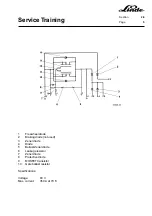
POWER STEERING CONTROL VALVE
The power steering control valve is mounted under the front cross member of the frame. At the end of the
steering wheel shaft is a taper with a pin. When the overhead guard is lowered, the steering column is
connected mechanically to the steering shaft through the internal gear coupling that engages in the taper,
i.e. in the pin.
The power steering control valve itself is essentially a rotor pump and a control valve built together into one
unit. The rotor pump is a gear-type pump that meters the hydraulic oil flow from the working hydraulic system
in accordance with the rotation of the steering wheel.
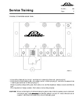
The steering control valve consists of the steering housing with the valve bore and the spool that can be turned
and moved axially in the bore. The axial movement of the spool modulates the working pressure and the
reversal of the oil flow depending upon the steering wheel direction of rotation.
The spool has a groove into which a pin engages. The pin is lifted and it engages in a sleeve with an annular
magnet when the steering wheel is operated and the spool is moving. This arrangement is used to control
a reed switch.
The reed switch allows a signal to go to the working hydraulic system electronics, which lets the pump motor
run at 600 rpm as soon as the steering wheel is operated.
Содержание 336 Series
Страница 2: ......
Страница 8: ...ServiceTraining ...
Страница 12: ...ServiceTraining Section 2 1 Page 4 ...
Страница 14: ...ServiceTraining Section 2 1 Page 6 2 1 4 TRACTIONMOTORDISASSEMBLY ...
Страница 19: ...ServiceTraining Section 2 2 Page 3 ...
Страница 21: ...ServiceTraining Section 2 2 Page 5 ...
Страница 27: ...ServiceTraining Section 2 2 Page 11 ...
Страница 28: ...ServiceTraining Section 2 2 Page 12 ...
Страница 33: ...ServiceTraining Section 2 4 Page 1 2 4 STEERING SYSTEM ...
Страница 35: ...ServiceTraining Section 2 4 Page 3 ...
Страница 37: ...ServiceTraining Section 2 4 Page 5 ...
Страница 39: ...ServiceTraining Section 2 4 Page 7 ...
Страница 41: ...ServiceTraining Section 2 4 Page 9 ...
Страница 45: ...ServiceTraining Section 2 4 Page 13 ...
Страница 47: ...ServiceTraining Section 2 4 Page 15 ...
Страница 53: ...ServiceTraining Section 2 5 Page 5 ...
Страница 54: ...ServiceTraining Section 2 5 Page 6 ...
Страница 69: ...ServiceTraining Section 2 6 Page 15 ...
Страница 70: ...ServiceTraining Section 2 6 Page 16 2 6 2 CONTACTORS 2 6 2 1 DIRECTIONALCONTACTORS Circuit diagram ...
Страница 74: ...ServiceTraining Section 2 6 Page 20 2 6 2 3 CIRCUIT BREAKER CONTACTOR 1K6 Circuit diagram ...
Страница 94: ...ServiceTraining Section 2 6 Page 40 ...
Страница 111: ...ServiceTraining Section 2 6 Page 57 Connector 1X6 1 15 V 2 Output signal 3 ...
Страница 124: ...ServiceTraining Section 2 6 Page 70 2 6 9 LOCATION OF CONNECTORS 2 6 9 1 LOCATION OF CONNECTORS TO SERIES 6 95 ...
Страница 126: ...ServiceTraining Section 2 6 Page 72 2 6 9 2 LOCATION OF CONNECTORS FROM SERIES 7 95 ...
Страница 128: ...ServiceTraining Section 2 6 Page 74 ...
Страница 145: ...Section 2 6 Page 91 ...
Страница 146: ......
Страница 147: ......
Страница 149: ...Section 2 6 Page 93 ...
Страница 150: ......
Страница 153: ...ServiceTraining Section 2 7 Page 3 ...
Страница 157: ...ServiceTraining Section 2 7 Page 7 ...
Страница 158: ...ServiceTraining Section 2 7 Page 8 ...
Страница 163: ...Section 2 9 Page 5 ...
Страница 164: ......
Страница 166: ...ServiceTraining Section 2 10 Page 2 ...
Страница 167: ......