


Service Training
Section
2.5
Page
3
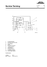
2.5.1.1.1
ACCELERATOR SENSOR OUTPUT SIGNALS
The accelerator output signal can be measured at connector 1X10.
Pin arrangement 1X10
1=(15 V)
2=(output signal)
3=(-)
4=(1S12 direction of travel)
5=(+ U
B
direction of travel)
6=Enable
The output signal can vary within the following range:
Neutral Position
Max. Reverse
Max. Forward
Output signal
measured (1X10/2-3)
7.5 V
11.25±0.65 V
3.75±0.65 V
The control range for the accelerator sensor is between 7.5 V and 11.25 V for reverse travel and between
7.5 V and 3.75 V for forward travel.
The following voltages are important for the control range when checking the traction control for proper
function.
Reverse
Forward
Neutral position:
7.5 V
7.5 V
Contactor makes:
8.2 V
6.8 V
Clocking starts:
8.4 V
6.6 V
End-point signal approx.:
11.25 V
3.75 V
Contactor breaks:
8.0 V
7.0 V
2.5.1.1.2
ADJUSTMENT OF THE NEUTRAL POSITION
After loosening both locknuts, adjust the connecting rod from the pedals to the accelerator sensor so that
the travel required to actuate the accelerator sensor microswitch is equal in both directions of travel.
Содержание 336 Series
Страница 2: ......
Страница 8: ...ServiceTraining ...
Страница 12: ...ServiceTraining Section 2 1 Page 4 ...
Страница 14: ...ServiceTraining Section 2 1 Page 6 2 1 4 TRACTIONMOTORDISASSEMBLY ...
Страница 19: ...ServiceTraining Section 2 2 Page 3 ...
Страница 21: ...ServiceTraining Section 2 2 Page 5 ...
Страница 27: ...ServiceTraining Section 2 2 Page 11 ...
Страница 28: ...ServiceTraining Section 2 2 Page 12 ...
Страница 33: ...ServiceTraining Section 2 4 Page 1 2 4 STEERING SYSTEM ...
Страница 35: ...ServiceTraining Section 2 4 Page 3 ...
Страница 37: ...ServiceTraining Section 2 4 Page 5 ...
Страница 39: ...ServiceTraining Section 2 4 Page 7 ...
Страница 41: ...ServiceTraining Section 2 4 Page 9 ...
Страница 45: ...ServiceTraining Section 2 4 Page 13 ...
Страница 47: ...ServiceTraining Section 2 4 Page 15 ...
Страница 53: ...ServiceTraining Section 2 5 Page 5 ...
Страница 54: ...ServiceTraining Section 2 5 Page 6 ...
Страница 69: ...ServiceTraining Section 2 6 Page 15 ...
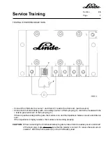
Страница 70: ...ServiceTraining Section 2 6 Page 16 2 6 2 CONTACTORS 2 6 2 1 DIRECTIONALCONTACTORS Circuit diagram ...
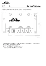
Страница 74: ...ServiceTraining Section 2 6 Page 20 2 6 2 3 CIRCUIT BREAKER CONTACTOR 1K6 Circuit diagram ...
Страница 94: ...ServiceTraining Section 2 6 Page 40 ...
Страница 111: ...ServiceTraining Section 2 6 Page 57 Connector 1X6 1 15 V 2 Output signal 3 ...
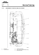
Страница 124: ...ServiceTraining Section 2 6 Page 70 2 6 9 LOCATION OF CONNECTORS 2 6 9 1 LOCATION OF CONNECTORS TO SERIES 6 95 ...
Страница 126: ...ServiceTraining Section 2 6 Page 72 2 6 9 2 LOCATION OF CONNECTORS FROM SERIES 7 95 ...
Страница 128: ...ServiceTraining Section 2 6 Page 74 ...
Страница 145: ...Section 2 6 Page 91 ...
Страница 146: ......
Страница 147: ......
Страница 149: ...Section 2 6 Page 93 ...
Страница 150: ......
Страница 153: ...ServiceTraining Section 2 7 Page 3 ...
Страница 157: ...ServiceTraining Section 2 7 Page 7 ...
Страница 158: ...ServiceTraining Section 2 7 Page 8 ...
Страница 163: ...Section 2 9 Page 5 ...
Страница 164: ......
Страница 166: ...ServiceTraining Section 2 10 Page 2 ...
Страница 167: ......