


INSTALLATIoN
WH45P
19
/42
rev 20-10
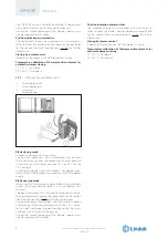
3.9.
Installations within vertical rigid wall
Refer to the section Construction supports characteristi-
cs p. 16 for further information.
Comply with the minimum distances indicated on section
Minimum distances p. 14.
before and after installation please perform a functional
test. Refer to section Mechanism type for further informa-
tion p. 7.
3.9.1.
Wall opening
A opening must be provided in the wall as indicated in the
table and in the drawing
3.9.2.
Damper positioning
Position the damper in the opening so that the side of the
closing mechanism extends as indicated in the table and
in the drawing.
Close the blade before installing the fire damper.
3.9.3.
Filling
Fill the space between the wall and the damper as indica-
ted in the table and in the drawing.
Sealing with concrete is not allowed.
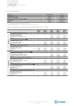
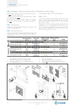
Fire resistance classi-
fication
“D” hole size
[mm]
Damper protrusion
from the wall “E”
[mm]
Wall minimum thick-
ness “S”
[mm]
Sealing
EI 90 S Installation within vertical rigid wall
Wall minimum density 500 kg/m³
EI 90 S
(500 Pa)
Da (Ø + 35) x (Ø + 35)
a (B+50) x (H+50)
(square hole)
215 + Lp
100
Rock wool 100 kg/m³
with infill plasterboard
(thickness 12.5 mm)
EI 120 S Installation within vertical rigid wall
Wall minimum density 500 kg/m³
EI 120 S
(500 Pa)
From Ø + 25
to Ø + 580
(square or circular hole)
215 + Lp
100
Mortar or plaster putty
sealing
EI 180 S Installation within vertical rigid wall
Wall minimum density 500 kg/m³
EI 180 S
(500 Pa)
From Ø + 25
to Ø + 35
(square or circular hole)
190 + Lp
100
Mortar sealing
WH45P
19
We reserve the right to make changes without prior notice