


INSTALLATIoN
WH45P
16
/42
rev 20-10
3.8.
Construction supports characteristics
The European standard for fire dampers foresees a preci-
se correlation between the wall/floor characteristics and
the fire resistance class obtained, as well as the correlation
between wall/floor used for the test and wall/floor used for
the actual installation.
The test results obtained on a type of wall/floor are valid
also for walls/floor of the same type but with greater thick-
ness and/or density than those used in the test.
For plasterboard walls, the test results are also valid for walls
with a greater number of plasterboard layers on each side.
As a result, the indicated thickness and density characteri-
stics are to be considered as minimum values.
The wall/floor in which the fire dampers are installed must
be fire class certified according to the standards foreseen
for the structure.
3.8.1.
Rigid walls
Can be made with aerated concrete blocks, poured con-
crete, concrete panels, perforated cell elements in concre-
te or brick in accordance with the following characteristics:
•
minimum thickness 100 mm;
•
minimum density 500 kg/m³.
The use of a reinforcing beam above the opening is recom-
mended for walls made from concrete blocks, bricks or in
concrete cell elements.
For walls built with perforated elements, it is also recom-
mended that the area of the opening be made from full
elements (for example aerated concrete blocks) to guaran-
tee the correct adhesion of the mortar.
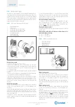
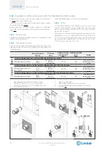
1.
Reinforcing beam
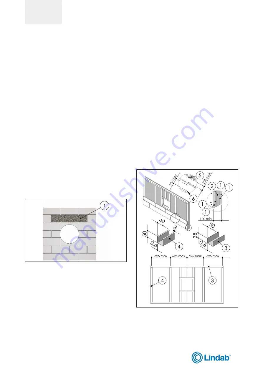
3.8.2.
Light plasterboard vertical walls
During testing, light plasterboard walls have been used
with the following characteristics:
•
U-shaped horizontal metal frame (50 mm) and C-shaped
vertical frame (49 mm) made from 0,6 mm thick sheet
metal;
•
vertical profiles placed with a maximum spacing of 625
mm between each other;
•
Filling made of rock wool with density up to 100 kg/m³
(optional);
•
Each side is made from two plasterboard layers 12,5 mm
thick, unalinged to avoid alignment between the joints
of the layer above and below.
The following indications are given for the installation walls:
•
metal profiles minimum width: 49 mm;
•
metal profiles minimum thickness: 0,6 mm;
•
vertical profiles placed with a maximum spacing of 625
mm between each other;
•
vertical profile fixing with selfthreading screws or by clin-
ching to the bottom horizontal profile and insertion in
the top horizontal profile;
•
profiles fixed using self-threading screws or by clinching
on every intersection.
•
installation of a frame around the damper with base and
height where shown in the installation instructions;
•
Filling made of rock wool with density up to 100 kg/m³
(optional);
•
each side is made from two plasterboard layers 12,5 mm
minumum thick, unalinged to avoid alignment between
the joints of the layer above and below.
•
the front plasterboards layers are fixed using long enou-
gh screws to pass through the lower plasterboard and
attach to the steel profile underneath.
1.
Plasterboard thickness 12,5 mm
2.
Rock wool density up to 100 kg/m³ (optional)
3.
Horizontal U-shaped profile
4.
Vertical C-shaped profile
5.
Self-drilling screw Ø 3,5 X 25 mm
6.
Self-drilling screw Ø 3,5 X 35 mm
WH45P
16
We reserve the right to make changes without prior notice