English
English
5
•
When the weld is stopped, the Cooler continues to
run for about 5min., after this time, it is automatically
switched off.
•
If the weld is restarted in a time lower than 5min.,
the Cooler continues to run.
The POWERTEC 425C PRO has the possibility to
switch the automatic work of the water cooler off and set
it in continuously work. If it is necessary to change the
water cooler kind of work, you should:
•
Switch off the POWERTEC 425C PRO.
•
Set the knob of the choice wire diameter selection
[16] in "1.0" position. Set the knob of the choice
welded material and gas mixture [17] in "CRNI
(98%AR 2%CO
2
)" position.
•
Switch the supply of the POWERTEC 425C PRO
on.
•
Within 15s switch the knob of the choice wire
diameter selection [16] in "1.2" position and the
knob of the choice welded material and gas mixture
[17] in "STEEL (100%CO
2
)" position – the water
cooler has been switched on and the display "V"
has lit "on".
If it is necessary to return the automatic work of the
water cooler you should do the foregoing actions again
(the display “V” has lit " 5'' ").
WARNING
The display "V" lights information about work mode of
the water cooler (5"/on) for 2 seconds after the supply of
the POWERTEC 425C PRO is switched on.
Welding Cables Connections
Insert the plug of the ground cable into the socket [10] or
[11]. The other end of this cable connects to the work
piece with the work clamp.
Connect the Euro connector to the welding torch with the
contact tip and torch liner suitable for the wire diameter
and material welded.
Loading the Electrode Wire
Open the side cover of the machine.
Unscrew the fastening cap of the sleeve.
Load the spool with the wire on the sleeve such that the
spool turns clockwise when the wire is fed into the wire
feeder.
Make sure that the spool locating pin goes into the fitting
hole on the spool.
Screw in the fastening cap of the sleeve.
Put on the wire roll using the correct groove
corresponding to the wire diameter.
Free the end of the wire and cut off the bent end making
sure it has no burr.
WARNING
Sharp end of the wire can hurt.
Rotate the wire spool clockwise and thread the end of
the wire into the wire feeder as far as the Euro socket.
Adjust force of pressure roll of the wire feeder properly.
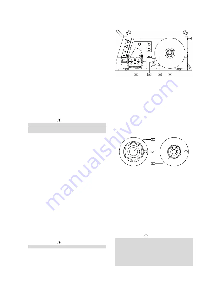
26. Sleeve.
27. Wire spool.
28. Electrode wire.
29. Feeding unit.
The machine is designed for wire spools of 15kg
(300mm).
Adjustments of Brake Torque of Sleeve
To avoid spontaneous unrolling of the welding wire the
sleeve is fitted with a brake.
Adjustment is carried by rotation of its screw M10, which
is placed inside of the sleeve frame after unscrewing the
fastening cap of the sleeve.
30. Fastening cap.
31. Adjusting screw M10.
32. Pressing spring.
Turning the screw M10 clockwise increases the spring
tension and you can increase the brake torque.
Turning the screw M10 counterclockwise decreases the
spring tension and you can decrease the brake torque.
After finishing of adjustment, you should screw in the
fastening cap again.
Adjusting of Pressure Roll Force
Pressure force is adjusted by turning the adjustment nut
clockwise to increase force, counterclockwise to
decrease force.
WARNING
If the roll pressure is too low the roll will slide on the wire.
If the roll pressure is set too high the wire may be
deformed, which will cause feeding problems in the
welding gun. The pressure force should be set properly.
Decrease the pressure force slowly until the wire just
begins to slide on the drive roll and then increase the
force slightly by turning of the adjustment nut by one
turn.
Содержание POWERTEC 305C PRO
Страница 145: ...Spare Parts Electrical Schematic Spare Parts Electrical Schematic 6 Electrical Schematic POWERTEC 305C PRO ...
Страница 146: ...Spare Parts Electrical Schematic Spare Parts Electrical Schematic 7 POWERTEC 355C PRO 425C PRO 425C PRO WATER ...
Страница 147: ...Spare Parts Electrical Schematic Spare Parts Electrical Schematic 8 WEEE ...


