8. Lightware Device Controller
UBEX series – Matrix Application Mode – User's Manual
99
8. Lightware Device Controller
UBEX series – Matrix Application Mode – User's Manual
99
MA
TRIX APPLIC
A
TION MODE
Applied F-series endpoint firmware package: v1.4.1 | Applied R-series endpoint firmware package: v1.4.1 | Applied MMU firmware package: v1.2.1 | LDC software: v1.34.0b2
8.19.2. Advanced Settings and Display Parameters
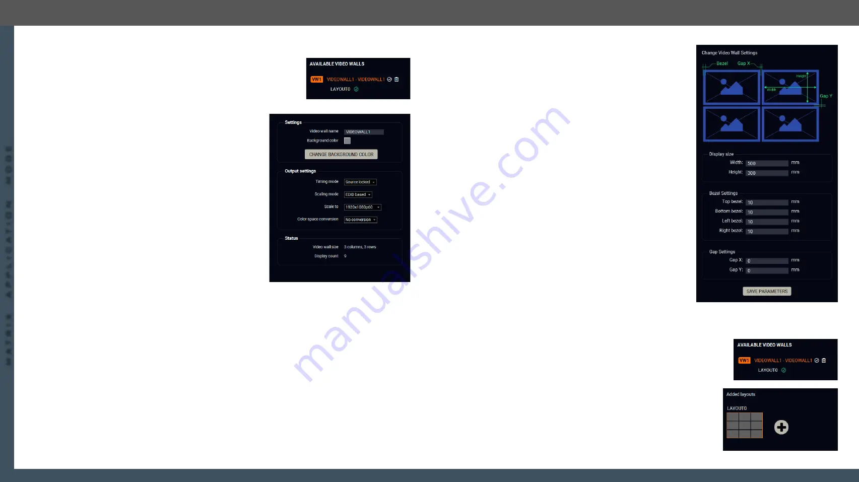
For editing the Advanced Settings and the Display parameters, click on
the
(Edit)
icon next to of the name of the video wall. When the icon
changes to
and the name changes to orange, the video wall is in
edit
mode
.
Advanced Settings
Clicking on the
Advanced settings
button results opening the
advanced settings of the video wall.
Settings
▪
Video wall name
;
▪
Change background color
: when no zone(s) are defined for
a new layout, the color which is set here will appear on
the display devices. The working method is the same
with the
function.
Output Settings
▪
Timing mode
(Free run / Source locked): see the more
details about it in the
recommended setting is the
Source locked
.
#timingmode
#freerun #sourcelocked
▪
Scaling mode
:
#scaler
–
Passthrough: the scaler is in pass-through mode.
–
Forced resolution: the scaling is active, the selected
value in the forced resolution option will be applied on the video signal;
–
EDID based: the scaler forces the resolution which is read out from the EDID of the connected sink
device.
▪
Forced resolution
: list of the available resolutions with refresh rate values. The selected one will be
applied on the video signal. See the available resolution in the
Resolutions of the Scaler / FRC
section.
▪
Image position
(Stretch / Fit / Center);
▪
Color space conversion
(No conversion / RGB / YUV 4:4:4 / YUV 4:2:2);
#csc #colorspace
Status
▪
Video wall size;
▪
Display count.
Display Parameters
Clicking on the
Display parameters
button results opening
the display parameter window where you can customize
parameters of the display devices installed in the video wall.
Display Size
The width and the height of the display in mm.
Bezel Settings
The size of the top, bottom, left, and right bezels in mm.
Gap Settings
The size of the gap between the displays in mm.
When it is completed, click on the
Save parameters
button.
8.19.3. Tutorial - Defining New Layouts and Zones
More different layouts can be defined for the same video wall.
When a new video wall is created, the default layout (LAYOUT0) is also created which has only one zone
(ZONE0). It contains all destination streams connected to the video wall. This section about how to create a
new layout and customize it for your current installation.
Step 1.
Click on the
(Edit)
icon next to of the name of the video wall
When the icon changes to
and the name changes to orange, the
video wall is in
edit mode
.
Step 2.
Click on the
icon in the
Added layouts
section to add a new
layout to the video wall. The schematic view of the video wall
appears on the top.


