38
39
Model: CLSC (Integrity Series)
Tools Required:
Standard Screwdriver, Phillips Screwdriver, Metric Hex Key Set, Side Cutters
Note:
The following Assembly Instructions show the console attached prior to TV installation. Follow all appropriate
steps when the console is not mounted.
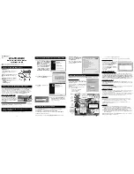
1. Remove the square END CAP (a) and two PLASTIC PLUGS (b)
located behind the console on the MAIN CONSOLE SUPPORT TUBE (c).
2. Remove the four SCREWS (d) that are used to fasten the console.
Carefully set the console aside, securing it so that it does not fall.
3. Locate the TV MOUNTING BRACKET (e). Unwrap the POWER SUPPLY
CORD (cc) and COAXIAL CABLE (dd) located within the CONSOLE
SUPPORT BRACKET TUBE (c). Route these cables through the opening
of the TV MOUNTING BRACKET (e).
Locate the AUDIO / VIDEO / I-R CABLE ASSEMBLY (f). Route this cable
assembly through the TV MOUNTING BRACKET (e) with the 2-connector
end coming out of the opening of the TV MOUNTING BRACKET.
4. Insert the TV MOUNTING BRACKET into the CONSOLE SUPPORT TUBE
and fasten with three SCREWS (h) and three WASHERS (i).
CAUTION:
Do not pinch any cables when inserting the TV
MOUNTING BRACKET into the CONSOLE SUPPORT TUBE.
5. Assemble the HINGED BRACKET (j) to the TV MOUNTING
BRACKET with the following provided hardware:
k.
screw
l.
steel washer
m.
nylon plastic washer
n.
nylon plastic shoulder washer
o.
steel
washer
p.
nut
a
b
c
d
e
cc
dd
f
f
g
j
p
o
n
m
l
k
h
i
11. Tilt the DISPLAY CONSOLE back into place. Replace the REAR
CONSOLE COVER (9) and secure it using the previously removed
four SCREWS (8). Tighten the screws securely. (8-10 ft. lbs.). Do not
overtighten the screws.
12. With the remaining TV BRACKET (20) oriented as shown, install it
to the back of the ATTACHABLE TV (21) using four SCREWS (22)
and WASHERS (23). Tighten the screws securely. (8-10 ft. lbs.)
Note:
Be sure the side holes of the TV BRACKET are oriented as
shown.
13. Position the TV BRACKETS (4 & 20) together and secure
them using one BOLT (24), WASHER (25) and NUT (26).
Leave the bolt and nut loose at this time.
Note:
Be sure the PIVOT POST of the TV BRACKET engages
onto
TV BRACKET.
14. Connect all cables to their corresponding jacks located on
the bottom of the ATTACHABLE TV. See the
Media
Connections
pages in this manual for detailed information.
Feed any excess media cable into the MAIN BRACKET (5).
15. Align the lowest side holes on the TV BRACKETS (4 & 20). Secure the TV
BRACKET into proper position using one SCREW (27) on each side.
16. Plug in and power on the TV. Refer to the
ATTACHABLE TV
Operation
Manual for proper TV setup.
For Achieve Console Units Only:
a. Remove the two SCREWS (A) and WASHERS (B) securing the
BOTTOM INSERT (C). Remove the BOTTOM INSERT. Do not
discard the SCREWS and WASHERS.
b. Locate the REMOTE CONTROL (D) and REMOTE BRACKET (E).
Feed the REMOTE CABLE (F) through the large access hole in the
REMOTE BRACKET (E). With the REMOTE CONTROL (D) and
REMOTE BRACKET (E) oriented as shown, secure them together
using one SCREW (G). Tighten the screw securely.
c. Carefully feed the REMOTE CABLE (F) through the opening in the
bottom of the CONSOLE (H) and through the back of the console.
Position the REMOTE BRACKET (E) into position replacing t he
BOTTOM INSERT (C). Secure the REMOTE BRACKET using the
previously removed SCREWS (A) and WASHERS (B).
H
16
D
A
A
C
B
16
E
F
G
A
A
B
21
20
22
23
21
27
27
24
25
26
4
27
21
20
Содержание ATV15-XXXA-02
Страница 1: ...1008767 0001 AA 15 ATTACHABLE TV ASSEMBLY INSTRUCTIONS ...
Страница 2: ......


