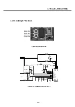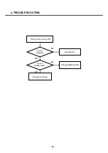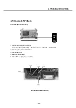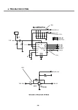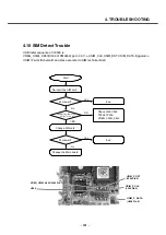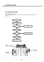
4.8 Power ON Trouble
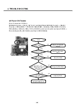
Power On sequence of U8500 is :
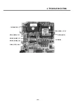
PWR(END) key press -> PM_ON_SW_N go to low(D603),PM6650 KPDPWR_N pin(24) -> PM6650
Power Up -> VREG_MSMC_1.375V(C406), VREG_MSME_1.8V(C408), VREG_MSMP_2.7V(C436),
VREG_MSMA_2.6V(C434), VREG_TCXO_2.85V(C416) power up and system reset assert to MSM ->
Phone booting and PS_HOLD(D400) assert High to PMIC(PM6650).
4. TROUBLE SHOOTING
- 98 -
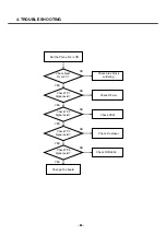
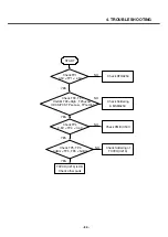
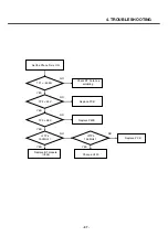
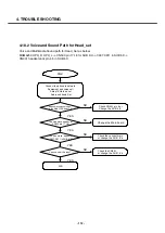
Start
Battery voltg . higher
than 3.28V?
Press PWR key
Keypad LED on?
D603 high to low
when key press?
VREG_MSMC_1.375V,
VREG_MSMP_2.7V, VREG_MSME_1.8V
VREG_TCXO_2.85V,
VREG_MSMA_2.6V
power up?
Is clock ok?
R413,C402 : 19.2M
X400 : 32.768Khz
Change the Main board
Change or charging the
Battery
Follow the LED trouble
shoot
Check the Diode
Change the Main board
Check the TXCO
NO
YES
YES
YES
YES
YES
NO
NO
NO
NO
Содержание U8500
Страница 1: ...Date February 2006 Issue 1 0 Service Manual Model U8500 Service Manual U8500 ...
Страница 20: ...3 TECHNICAL BRIEF 21 ...
Страница 32: ...3 TECHNICAL BRIEF 33 Figure 3 5 6 1 GSM PA functional block diagram ...
Страница 35: ...3 TECHNICAL BRIEF 36 Figure 3 5 10 1 Bluetooth system architecture ...
Страница 50: ...3 TECHNICAL BRIEF 51 Figure 3 10 3 2 1 PM6650 Functional Block Diagram ...
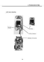
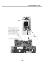
Страница 110: ...4 TROUBLE SHOOTING 111 R605 R606 receiver signal serial resistor Receiver CN600 50pin LCD connector FPCB for LCD Module ...
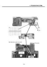
Страница 112: ...4 TROUBLE SHOOTING 113 R605 R606 receiver signal serial resistor CN600 50pin LCD connector CN901 C907 C911 ...
Страница 114: ...4 TROUBLE SHOOTING 115 Loud Speaker U502 U503 Amp ...
Страница 118: ...4 TROUBLE SHOOTING 119 C200 C201 for MIC serial capacitor ...
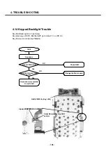
Страница 121: ...4 TROUBLE SHOOTING 122 Q404 Q403 Q402 VBATT GND ...
Страница 128: ...5 DOWNLOAD 129 5 Choose a Module Image file after clicking on the Browse button U8500 U8500 U8500 U8500 U8500 U8500 ...
Страница 132: ...5 DOWNLOAD 133 Downloading the AMSS Modem image Rebooting and waiting for a while Performing NV restore ...
Страница 134: ...5 DOWNLOAD 135 Download of Module image in progress Download process has completed successfully ...
Страница 143: ...6 BLOCK DIAGRAM 144 6 3 Interface Diagram U8500 Interface Diagram ...
Страница 145: ... 146 ...
Страница 154: ... 155 U8500 8 PCB LAYOUT ...
Страница 155: ... 156 8 PCB LAYOUT U8500 ...
Страница 156: ... 157 8 PCB LAYOUT ...
Страница 157: ... 158 8 PCB LAYOUT ...
Страница 158: ... 159 U8500 8 PCB LAYOUT ...
Страница 159: ... 160 U8500 8 PCB LAYOUT ...
Страница 166: ...9 CALIBRATION 167 Click START button U8500 U8500_ver1 1 U8500 U8500 Click U8500 ...
Страница 167: ... 168 ...
Страница 169: ... 170 ...
Страница 194: ...Note ...
Страница 195: ...Note ...

