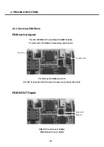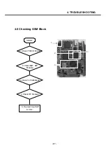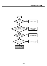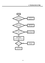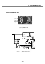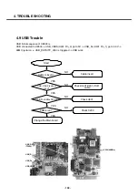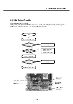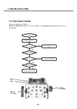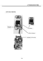
4.6.4 Checking PAM Block
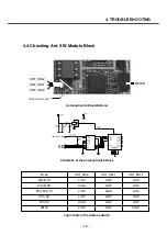
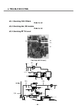
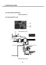
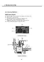
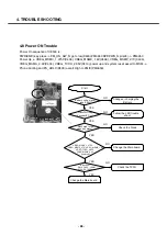
PAM Control Signal
TP1. GSM_PA_RAMP : Power Amp Gain Control. typically, 0.5V < Vapc < 2.6V,
TP2. GSM_PA_EN : Power Amp Enable
(Power ON : higher than 2.5V , Power OFF : lower than 0.7V)
TP3. GSM_PA_BAND : Power Amp Band Selection Control
(GSM Mode : lower than 0.7V , DCS/PCS Mode : higher than 2.5V)
TP4. +VPWR : PAM Supply Voltage Vcc higher than 3.28V
4. TROUBLE SHOOTING
- 92 -
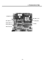
TP1
TP2
TP3
TP4
Test Point (RF Tx Level)
100
R1041
C1102
68p
C1101
15p
0.01u
C1098
C1100
68u
R1050
0
R1042
15K
GND6
12
13
GND7
GND8
14
GND9
16
4
GSM_IN
11
GSM_OUT
21
PGND
19
RSVD_GND
VAPC
20
17
VBATT
2
VCC1A
6
VCC1B
SKY77328
U1005
BS
1
DCS_PCS_IN
3
15
DCS_PCS_OUT
ENABLE
18
GND1
5
GND2
7
8
GND3
GND4
9
10
GND5
R1049
0
L1025
NA
C1103
15p
0.01u
C1071
0.01u
C1104
L1026
NA
R1044
100
C1070
10u
GSM_PA_RAMP
GSM_PA_EN
GSM_PA_BAND
+VPWR
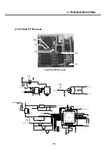
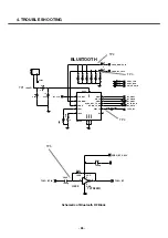
Schematic of PAM block
TP4
TP4
TP1
TP2
TP3
Содержание U8500
Страница 1: ...Date February 2006 Issue 1 0 Service Manual Model U8500 Service Manual U8500 ...
Страница 20: ...3 TECHNICAL BRIEF 21 ...
Страница 32: ...3 TECHNICAL BRIEF 33 Figure 3 5 6 1 GSM PA functional block diagram ...
Страница 35: ...3 TECHNICAL BRIEF 36 Figure 3 5 10 1 Bluetooth system architecture ...
Страница 50: ...3 TECHNICAL BRIEF 51 Figure 3 10 3 2 1 PM6650 Functional Block Diagram ...
Страница 110: ...4 TROUBLE SHOOTING 111 R605 R606 receiver signal serial resistor Receiver CN600 50pin LCD connector FPCB for LCD Module ...
Страница 112: ...4 TROUBLE SHOOTING 113 R605 R606 receiver signal serial resistor CN600 50pin LCD connector CN901 C907 C911 ...
Страница 114: ...4 TROUBLE SHOOTING 115 Loud Speaker U502 U503 Amp ...
Страница 118: ...4 TROUBLE SHOOTING 119 C200 C201 for MIC serial capacitor ...
Страница 121: ...4 TROUBLE SHOOTING 122 Q404 Q403 Q402 VBATT GND ...
Страница 128: ...5 DOWNLOAD 129 5 Choose a Module Image file after clicking on the Browse button U8500 U8500 U8500 U8500 U8500 U8500 ...
Страница 132: ...5 DOWNLOAD 133 Downloading the AMSS Modem image Rebooting and waiting for a while Performing NV restore ...
Страница 134: ...5 DOWNLOAD 135 Download of Module image in progress Download process has completed successfully ...
Страница 143: ...6 BLOCK DIAGRAM 144 6 3 Interface Diagram U8500 Interface Diagram ...
Страница 145: ... 146 ...
Страница 154: ... 155 U8500 8 PCB LAYOUT ...
Страница 155: ... 156 8 PCB LAYOUT U8500 ...
Страница 156: ... 157 8 PCB LAYOUT ...
Страница 157: ... 158 8 PCB LAYOUT ...
Страница 158: ... 159 U8500 8 PCB LAYOUT ...
Страница 159: ... 160 U8500 8 PCB LAYOUT ...
Страница 166: ...9 CALIBRATION 167 Click START button U8500 U8500_ver1 1 U8500 U8500 Click U8500 ...
Страница 167: ... 168 ...
Страница 169: ... 170 ...
Страница 194: ...Note ...
Страница 195: ...Note ...


