9
Handling devices that are sensitive to electrostatic discharge
Any computer part containing transistors or integrated circuits (ICs) should be considered sensitive to
electrostatic discharge (ESD). ESD damage can occur when there is a difference in charge between
objects. Protect against ESD damage by equalizing the charge so that the machine, the part, the work mat,
and the person handling the part are all at the same charge.
Note
Use product-specific ESD procedures when they exceed the requirements noted here.
Make sure that the ESD protective devices you use have been certified (ISO9000) as fully effective.
· When handling ESD-sensitive parts :
1. Keep the parts in protective packages until they are inserted into the product.
2. Wear a grounded wrist strap against your skin to eliminate static on your body.
3. Prevent the part from touching your clothing. Most clothing retains a charge even when you are wearing
a wrist strap.
4. Use the black side of a grounded work mat to provide a static-free work surface. The mat is especially
useful when handling ESD-sensitive devices.
5. Select a grounding system, such as those listed below, to provide protection that meets the specific
service requirement.
Note
The use of a grounding system is desirable but not required to protect against ESD damage.
a. Attach the ESD ground clip too any frame ground, ground braid, or green-wire ground.
b. Use an ESD ground or reference point when working on a double-insulated or battery-operated
system. You can use coax or connector-outside shells on these systems.
c. Use the round ground-prong of the AC plug on AC-operated computers.
Ch1. Service information
Grounding requirements
Electrical grounding of the computers is required for operator safety and correct system function.
Proper grounding of the electrical outlet can be verified by a certified electrician.
Содержание R580 Series U.ARC3BA9
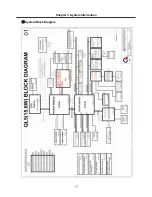
Страница 17: ...17 System Block Diagram Chapter 3 System information ...
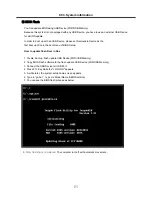
Страница 23: ...23 12 It selects the Exit Saving Change and it stores system a settings and the reboot Ch3 System information ...
Страница 25: ...25 Ch3 System information c Select Disc Image or Saved Project d Select File Format as Image Files iso ...
Страница 26: ...26 Ch3 System information e Open Image File iso which is sent from LGE f Tab Burn then burning will be started ...
Страница 27: ...27 Ch3 System information g Burn process completed as below and tab OK ...
Страница 30: ...30 Ch3 System information 5 After flashing is completed you can see the PASS on your screen and reboot your PC ...
Страница 57: ...57 3 Remove the Hook Ch5 Removing and replacing a part Hook Hook Hook Hook 4 Remove the Memory ...
Страница 60: ...60 Ch5 Removing and replacing a part 5 Remove the HDD Shield ...
Страница 63: ...63 Ch5 Removing and replacing a part 3 Remove the WLAN Module ...
Страница 66: ...66 3 Remove the ODD Ch5 Removing and replacing a part 4 Remove the ODD Bezel Bezel ...
Страница 69: ...69 69 Ch5 Removing and replacing a part 5 Remove the Keyboard 6 Remove the Retainer ...
Страница 71: ...71 71 Ch5 Removing and replacing a part 3 Remove the Display Module ...
Страница 74: ...74 Ch5 Removing and replacing a part 3 Remove the Keyboard deck ...
Страница 79: ...79 Ch5 Removing and replacing a part 3 Remove the Mainboard Case ...
Страница 86: ...86 Ch5 Removing and replacing a part 3 Remove the Hinge Cap ...
Страница 98: ...NLCD07 NLCD05 NLCD09 NLCD03 NLCD01 NLCD04 NLCD08 NLCD02 NWEBC01 ...
Страница 100: ...NMINI02 NMINI01 NKDECK01 NKDECK02 NRTN01 NKEYBD01 ...
Страница 102: ...NMRY01 NMRY01 NMINI04 NTHMO01 NRBS01 NMINI03 NCPU01 NMLB01 ...
Страница 105: ...NCVR02 NCVR03 NCVR01 NHDD02 NHDD01 NBATT01 NODD02 NODD01 NBOTM01 NBOTM03 NHDD03 NBOTM02 ...


