Diagnostic aids
3-9
4060-
xxx
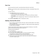
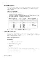
SDRAM Memory Test
The purpose of this test is to check the validity of SDRAM, both standard and optional. The test
writes patterns of data to SDRAM to verify that each bit in memory can be set and read correctly.
To run the SDRAM Memory Test:
1.
Select
SDRAM Memory Test
from the menu. The power indicator blinks indicating the test is in
progress.
2.
Press
Return/Stop
to exit the test.
P:
######
represents the number of times the memory test has passed and finished successfully.
Initially 000000 displays with the maximum pass count being 999,999.
F:
#####
represents the number of times the memory test has failed and finished with errors. Initially
00000 displays with the maximum fail count being 99,999.
Once the maximum pass count or fail count is reached, the test is stopped, the power indicator is
turned on solid, and the final results display. If the test fails, the message SDRAM Error, displays for
approximately three seconds and the failure count increases by 1.
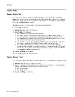
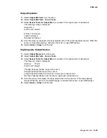
ROM Memory Test
The ROM Memory Test is used to check the validity of the controller board code and fonts.
To run the ROM Memory Test:
1.
Select
ROM Memory Test
from the menu. P and F represent the same numbers for DRAM.
The power indicator blinks indicating the test is in process. The test runs continuously.
Each time the test finishes, the screen updates with the result. If the test passes, the Pass
Count increases by 1, however if the test fails, one of the following messages displays for
approximately three seconds: ROM Checksum Error or ROM Burst Read Error. Once the
maximum pass count or fail count is reached, the test stops with the power indicator on solid.
The results appear on the screen.
2.
Press
Return/Stop
to exit the test.
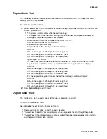
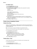
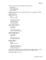
Parallel Wrap Test
This test is used with a wrap plug to check operation of the parallel port hardware. Each parallel
signal is tested.
To run the Parallel Wrap Test:
1.
Disconnect the parallel interface cable and install the wrap plug (P/N 1319128).
2.
Select
Parallel Wrap Test
from the menu. The power indicator blinks indicating the test is in
progress. The test runs continuously until canceled.
Each time the test finishes, the screen updates. If the test passes, the Pass Count increases
by 1, however if the test fails, a message displays for approximately three seconds. Once the
maximum count is reached the test stops. The power indicator goes on solid and the final
results display.
3.
Press
Return/Stop
to exit the test.
Содержание T63 Series
Страница 13: ...Laser notices xiii 4060 xxx Japanese Laser Notice ...
Страница 14: ...xiv Service Manual 4060 xxx Korean Laser Notice ...
Страница 34: ...1 16 Service Manual 4060 xxx ...
Страница 218: ...4 64 Service Manual 4060 xxx ...
Страница 236: ...6 2 Service Manual 4060 xxx ...
Страница 238: ...7 2 Service Manual 4060 xxx Assembly 1 Covers ...
Страница 240: ...7 4 Service Manual 4060 xxx Assembly 2 Frame 1 5 2 1 3 4 3 4 8 6 7 ...
Страница 250: ...7 14 Service Manual 4060 xxx Assembly 8 Paper feed multipurpose feeder 3 11 7 5 9 2 6 4 8 1 7 13 5 12 10 ...
Страница 252: ...7 16 Service Manual 4060 xxx Assembly 9 Paper feed alignment 3 2 1 4 ...
Страница 254: ...7 18 Service Manual 4060 xxx Assembly 10 Integrated paper tray 250 sheet 3 11 7 5 9 2 10 6 4 8 1 ...
Страница 256: ...7 20 Service Manual 4060 xxx Assembly 11 Integrated paper tray 500 sheet 3 11 7 5 9 2 10 6 4 8 1 ...
Страница 258: ...7 22 Service Manual 4060 xxx Assembly 12 Drives Main drive and developer drive 3 2 4 1 7 6 5 ...
Страница 260: ...7 24 Service Manual 4060 xxx Assembly 13 Hot roll fuser 3 7 5 2 6 4 1 5 8 7 9 ...
Страница 262: ...7 26 Service Manual 4060 xxx Assembly 14 Transfer charging 3 2 4 1 5 6 7 9 10 8 ...
Страница 264: ...7 28 Service Manual 4060 xxx Assembly 15 Electronics power supplies 3 7 5 2 6 4 1 ...
Страница 266: ...7 30 Service Manual 4060 xxx Assembly 16 Electronics card assemblies 3 1 4 5 6 9 2 4 7 8 10 ...
Страница 268: ...7 32 Service Manual 4060 xxx Assembly 17 Electronics shields ...
Страница 270: ...7 34 Service Manual 4060 xxx Assembly 18 Cabling diagrams 1 3 1 2 4 5 6 7 8 7 4 ...
Страница 272: ...7 36 Service Manual 4060 xxx Assembly 19 Cabling diagrams 2 HVPS LVPS 3 5 4 1 2 6 ...
Страница 274: ...7 38 Service Manual 4060 xxx Assembly 20 Cabling diagrams 3 3 4 5 6 1 2 400 410 2 000 010 1 1 2 200 210 2 7 ...
Страница 276: ...7 40 Service Manual 4060 xxx Assembly 21 250 sheet paper tray ...
Страница 278: ...7 42 Service Manual 4060 xxx Assembly 21 cont 250 sheet paper tray 43 41 42 38 36 34 39 37 35 40 46 45 44 ...
Страница 284: ...7 48 Service Manual 4060 xxx Assembly 23 Duplex option 1 ...
Страница 286: ...7 50 Service Manual 4060 xxx Assembly 24 Envelope feeder 3 11 7 13 5 9 2 10 6 4 12 8 14 1 ...
Страница 288: ...7 52 Service Manual 4060 xxx Assembly 25 Output expander ...
Страница 290: ...7 54 Service Manual 4060 xxx Assembly 25 cont Output expander ...
Страница 292: ...7 56 Service Manual 4060 xxx Assembly 26 High capacity output expander ...
Страница 296: ...7 60 Service Manual 4060 xxx Assembly 27 5 bin mailbox ...
Страница 298: ...7 62 Service Manual 4060 xxx Assembly 27 cont 5 bin mailbox ...
Страница 300: ...7 64 Service Manual 4060 xxx Assembly 28 High capacity feeder 1 ...
Страница 304: ...7 68 Service Manual 4060 xxx Assembly 30 High capacity feeder 3 3 11 7 13 9 15 2 10 6 4 12 8 14 1 1 3 5 ...
Страница 306: ...7 70 Service Manual 4060 xxx Assembly 31 High capacity feeder 4 3 11 7 13 18 5 16 9 15 2 10 6 17 4 12 8 14 19 1 4 ...
Страница 308: ...7 72 Service Manual 4060 xxx Assembly 32 High capacity feeder 5 3 11 7 5 9 2 10 6 4 12 8 1 10 10 10 12 ...
Страница 314: ...7 78 Service Manual 4060 xxx Assembly 35 StapleSmart finisher I 3 11 7 13 5 16 9 15 2 10 6 17 4 12 8 14 1 5 18 ...
Страница 316: ...7 80 Service Manual 4060 xxx Assembly 36 StapleSmart finisher 2 3 11 7 13 5 9 2 10 6 4 12 8 14 1 4 4 4 4 ...
Страница 320: ...7 84 Service Manual 4060 xxx Assembly 38 StapleSmart finisher 4 1 ...
Страница 344: ...I 20 Service Manual 4060 xxx ...
Страница 345: ......

