Diagnostic information
2-79
4060-
xxx
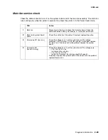
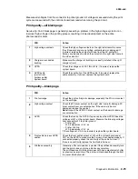
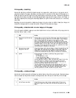
Measure all voltages from the connector to printer ground. All voltages measured during the print
cycle are measured with the controller board removed while running the print test.
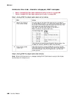
Print quality—all black page
Service tip: An all black page is generally caused by a problem in the high voltage system or an
incorrect high voltage in the printing process resulting in toner development on the entire
photoconductor drum.
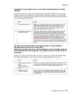
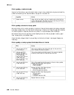
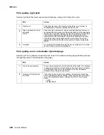
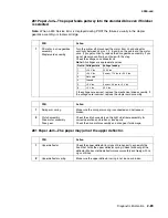
Print quality—blank page.
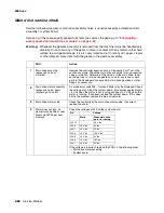
FRU
Action
1
High voltage contacts
Check the high voltage contacts on the right side frame to ensure
they fit securely and are not pitted, contaminated, or damaged. If
incorrect, replace the contact with one from the HV contact kit.
Screws are included to attach the contacts to the right side frame in
the HV contact kit.
2
Charge roll conductive
bushing
Make sure the charge roll bushing is correctly installed in the right
charge roll arm.
3
HVPS
Check the voltages on J22-1 thru J22-8. If incorrect, replace the
system board.
4
HVPS cable
(part of front
harness cable)
System board
Check the continuity of the HVPS cable. If incorrect, replace the
cable assembly. If correct, replace the system board.
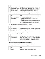
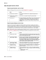
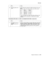
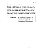
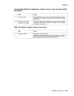
FRU
Action
1
Print cartridge
Check the print cartridge for damage, especially the PC drum contact
on the cartridge.
2
High voltage contact
Check the PC drum contact on the right side frame for damage, PC
drum contact wear or contamination. If the contact is bent or
damaged, replace the contact.
Note:
Inspect the HVPS PC drum contact on the board for damage
or contamination.
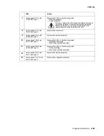
3
HVPS
Check the fuse on the HVPS. If open, replace the HVPS. Check the
voltages at J22 on the system board. Measure the following voltages
from connector J22 to printer ground:
• Printer Idle
J22-5 me24 V dc
• Printer Printing
J22-5 me24 V dc
If the voltages at J10-5 are incorrect, replace the system board.
4
Front cable harness HVPS
section
Check the front cable harness at J22 on the system board and at
CN1 on the HVPS to make sure the harness is connected properly. If
connected properly, check the continuity of the cable harness. If
there is no continuity, replace the front cable harness.
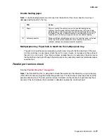
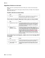
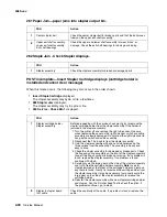
5
Printhead assembly
Generally a 93
x
service error is posted if the printhead assembly fails
and the printer does not give a blank copy symptom.
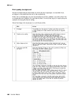
The printhead used in the printer does not have a mechanical shutter
as previous laser printers. The printer is interlocked through the front
top cover interlock switch.
Содержание T63 Series
Страница 13: ...Laser notices xiii 4060 xxx Japanese Laser Notice ...
Страница 14: ...xiv Service Manual 4060 xxx Korean Laser Notice ...
Страница 34: ...1 16 Service Manual 4060 xxx ...
Страница 218: ...4 64 Service Manual 4060 xxx ...
Страница 236: ...6 2 Service Manual 4060 xxx ...
Страница 238: ...7 2 Service Manual 4060 xxx Assembly 1 Covers ...
Страница 240: ...7 4 Service Manual 4060 xxx Assembly 2 Frame 1 5 2 1 3 4 3 4 8 6 7 ...
Страница 250: ...7 14 Service Manual 4060 xxx Assembly 8 Paper feed multipurpose feeder 3 11 7 5 9 2 6 4 8 1 7 13 5 12 10 ...
Страница 252: ...7 16 Service Manual 4060 xxx Assembly 9 Paper feed alignment 3 2 1 4 ...
Страница 254: ...7 18 Service Manual 4060 xxx Assembly 10 Integrated paper tray 250 sheet 3 11 7 5 9 2 10 6 4 8 1 ...
Страница 256: ...7 20 Service Manual 4060 xxx Assembly 11 Integrated paper tray 500 sheet 3 11 7 5 9 2 10 6 4 8 1 ...
Страница 258: ...7 22 Service Manual 4060 xxx Assembly 12 Drives Main drive and developer drive 3 2 4 1 7 6 5 ...
Страница 260: ...7 24 Service Manual 4060 xxx Assembly 13 Hot roll fuser 3 7 5 2 6 4 1 5 8 7 9 ...
Страница 262: ...7 26 Service Manual 4060 xxx Assembly 14 Transfer charging 3 2 4 1 5 6 7 9 10 8 ...
Страница 264: ...7 28 Service Manual 4060 xxx Assembly 15 Electronics power supplies 3 7 5 2 6 4 1 ...
Страница 266: ...7 30 Service Manual 4060 xxx Assembly 16 Electronics card assemblies 3 1 4 5 6 9 2 4 7 8 10 ...
Страница 268: ...7 32 Service Manual 4060 xxx Assembly 17 Electronics shields ...
Страница 270: ...7 34 Service Manual 4060 xxx Assembly 18 Cabling diagrams 1 3 1 2 4 5 6 7 8 7 4 ...
Страница 272: ...7 36 Service Manual 4060 xxx Assembly 19 Cabling diagrams 2 HVPS LVPS 3 5 4 1 2 6 ...
Страница 274: ...7 38 Service Manual 4060 xxx Assembly 20 Cabling diagrams 3 3 4 5 6 1 2 400 410 2 000 010 1 1 2 200 210 2 7 ...
Страница 276: ...7 40 Service Manual 4060 xxx Assembly 21 250 sheet paper tray ...
Страница 278: ...7 42 Service Manual 4060 xxx Assembly 21 cont 250 sheet paper tray 43 41 42 38 36 34 39 37 35 40 46 45 44 ...
Страница 284: ...7 48 Service Manual 4060 xxx Assembly 23 Duplex option 1 ...
Страница 286: ...7 50 Service Manual 4060 xxx Assembly 24 Envelope feeder 3 11 7 13 5 9 2 10 6 4 12 8 14 1 ...
Страница 288: ...7 52 Service Manual 4060 xxx Assembly 25 Output expander ...
Страница 290: ...7 54 Service Manual 4060 xxx Assembly 25 cont Output expander ...
Страница 292: ...7 56 Service Manual 4060 xxx Assembly 26 High capacity output expander ...
Страница 296: ...7 60 Service Manual 4060 xxx Assembly 27 5 bin mailbox ...
Страница 298: ...7 62 Service Manual 4060 xxx Assembly 27 cont 5 bin mailbox ...
Страница 300: ...7 64 Service Manual 4060 xxx Assembly 28 High capacity feeder 1 ...
Страница 304: ...7 68 Service Manual 4060 xxx Assembly 30 High capacity feeder 3 3 11 7 13 9 15 2 10 6 4 12 8 14 1 1 3 5 ...
Страница 306: ...7 70 Service Manual 4060 xxx Assembly 31 High capacity feeder 4 3 11 7 13 18 5 16 9 15 2 10 6 17 4 12 8 14 19 1 4 ...
Страница 308: ...7 72 Service Manual 4060 xxx Assembly 32 High capacity feeder 5 3 11 7 5 9 2 10 6 4 12 8 1 10 10 10 12 ...
Страница 314: ...7 78 Service Manual 4060 xxx Assembly 35 StapleSmart finisher I 3 11 7 13 5 16 9 15 2 10 6 17 4 12 8 14 1 5 18 ...
Страница 316: ...7 80 Service Manual 4060 xxx Assembly 36 StapleSmart finisher 2 3 11 7 13 5 9 2 10 6 4 12 8 14 1 4 4 4 4 ...
Страница 320: ...7 84 Service Manual 4060 xxx Assembly 38 StapleSmart finisher 4 1 ...
Страница 344: ...I 20 Service Manual 4060 xxx ...
Страница 345: ......

