Lexicon MPX G2 Скачать руководство пользователя страница 32

MPX G2

 Service Manual

4-20

6.  Move the cable from the Left Main Output jack to the Right Main Output Jack.
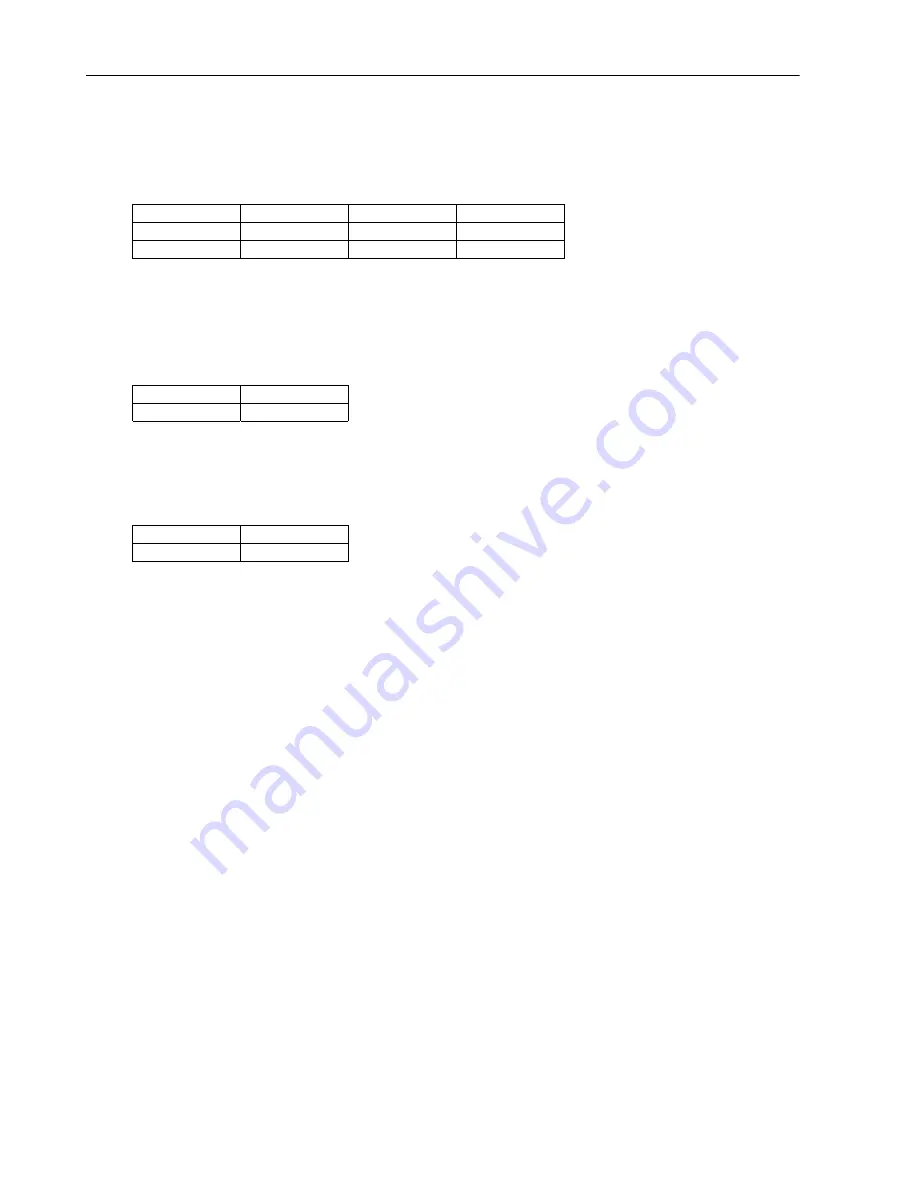
7.  Verify the output level reading is between 1.06 to -1.56 dBu (875 to 647 mVRMS) at the following

frequency settings.

20,000Hz

16,000Hz

12,000Hz

10,000Hz

4,000Hz

2,000Hz

250Hz

100Hz

60Hz

20Hz

8.  Enable the Lo pass filters on the analyzer (f30kHz or 20kHz).

Crosstalk Left/Right Measurements:
1.  Move the cable from the Right Main Output Jack to the Left Main Output Jack.
2.  Verify the crosstalk output level reading is between -62.94 to -120 dBu (552 to 1.2 uVRMS) at the

following frequency settings.

20,000Hz

10,000Hz

997Hz

100Hz

3.  Move the cable from the Right Insert Return jack to the Left Insert Return jack.
4.  Move the cable from the Left Main Output jack to the Right Main Output Jack.
5.  Verify the crosstalk output level reading is between -62.94 to -120 dBu (552 to 1.2 uVRMS) at the

following frequency settings.

20,000Hz

10,000Hz

997Hz

100Hz

THD+N Measurement with Soft Sat On:
Because you have to leave the Development Row in this test to turn Soft Sat on, access to the
Development Row will have to be recalled and the settings for the DSP will have to be reset. Please
perform the following steps to insure proper set for this section of the test.

Setup:

1.  Press the System button until the display reads: System select Development.
2.  Turn the knob CCW until the display reads: System select Audio.
3.  Press the Yes button once. The display reads: Audio Soft Sat Off. Turn the knob CW On.
4.  Press the No button once to get back to the System Page. Select Audio.
5.  The MPX G2 now has to be placed in a test program called Development. This will require several

steps before the remaining settings for the Performance Section are set properly.
5.1.  Press the System button. The display reads: System select Audio.
5.2.  Turn the knob CW until the display reads: System select MIDI.
5.3.  Press the Yes button 4 times until the display reads: MIDI Ctl Send None = None.
5.4.  Press the Options button. The display reads: MIDI Reset Press YES.
5.5.  Press and hold the Effect 1 button until the display reads: Debug Mode then release.
5.6.  Press the Options button. The display reads: MIDI Ctl Send None=None.
5.7.  Press the No button 4 times until the display reads: System Select MIDI.
5.8.  Turn the knob CW until the display reads: System select Development. The Development

Diagnostics Menu will now be available.

6.  Connect an audio input cable between the Low Distortion Oscillator and the MPX G2 Left Insert Return

jack.

7.  Connect an audio output cable from the Left Main 1/4 Output jack on the rear of the MPX G2 to the

Distortion Analyzer.

Check the following Parameters in the Development Row to insure settings are correct.

1.  Press the System button until the display will reads: System Select Development.
2.  Press the Yes button once. The display reads: Devel Split. Off. Turn the knob CCW to Off 0.
3.  Press the Yes button 2 times. The display reads: Devel Sum On 1. Turn the knob CCW to Off 0.

Содержание MPX G2

Страница 1: ...MPX G2 Guitar Effects Processor Service Manual ...

Страница 2: ...enance Instructions in this accompanying literature Notice This equipment generates and uses radio frequency energy and if not installed and used properly that is in strict accordance with the manufacturer s instructions may cause interference to radio and television reception It has been type tested and found to comply with the limits for a Class B computing device in accordance with the specific...

Страница 3: ...or polarization of the unit s power cord Not applicable in Canada Power Cord Protection Route power supply cords so that they are not likely to be walked on or pinched by items placed on or against them paying particular attention to cords at plugs convenience receptacles and the point at which they exit from the unit Nonuse Periods Unplug the power cord of the unit from the outlet when the unit i...

Страница 4: ...GEROUS PROCEDURE WARNINGS Warnings such as the example below precede potentially dangerous procedures throughout this manual Instructions contained in the warnings must be followed WARNING Dangerous voltages capable of causing death are present in this instrument Use extreme caution when handling testing and adjusting SAFETY SYMBOLS General definitions of safety symbols used on equipment or in man...

Страница 5: ... lexicon com kbase index asp 5 1 Diagnostics 5 1 Power On Diagnostics 5 1 Error Indication 5 1 Test Descriptions 5 2 Functional Tests Extended Diagnostics 5 5 Functional Test Descriptions 5 6 Switch Test 5 6 Front Panel Pots 5 8 LED Test 5 9 Display Character Test 5 9 Display Block Test 5 10 Auto Test Execution 5 11 Burn In Loop 5 11 Footpedal Test 5 12 MIDI Test 5 13 DRAM Test 5 14 WCS Test 5 15 ...

Страница 6: ...e Block 6 3 Dynamic Gain 6 3 Send 6 4 Aux Inputs including Speaker Simulator 6 5 Output 6 6 Supplies 6 6 Digital 6 7 ARCHITECTURE 6 7 SCHEMATIC WALK THROUGH 6 14 DETAILS 6 17 Chapter 7 Parts List 7 1 Main Board 7 1 Display Board 7 5 Front Panel Input Board 7 6 Chassis Mechanical 7 6 Packaging Miscellaneous 7 7 Power Cords 7 7 Chapter 8 Schematics and Drawings 8 1 Schematics 8 1 Drawings 8 1 ...

Страница 7: ...les dependent on your signal source 2 shielded audio cables with 1 4 plugs on one end T S for single ended T R S for balanced and appropriate connections on the opposite ends for connection to Low Distortion Oscillator RCA male to male braided shield style cable 1 MIDI cable male 5 pin DIN to male 5 pin DIN 3ft minimum 1 Low Distortion Oscillator with a single ended or balanced output 600 output i...

Страница 8: ......

Страница 9: ...No equipment will be accepted without Return Authorization from Lexicon If Lexicon recommends that a MPX G2 be returned for repair and you choose to return the unit to Lexicon for service Lexicon assumes no responsibility for the unit in shipment from the customer to the factory whether the unit is in or out of warranty All shipments must be well packed using the original packing materials if poss...

Страница 10: ......

Страница 11: ...nput to Send with Noise Gate on 97dB unweighted typical instrument to main outputs in Bypass Sample rate 44 1kHz Return Mix When the Return Mix option is selected MPX G2 will mix the analog Aux inputs with the post converter output signal from the DSP Throughput delay without send return loop Input to Main Output 3ms nominal Internal Audio Data Paths Conversion 24 bit A D 24 bit D A DSP 32 bits Co...

Страница 12: ......

Страница 13: ...ate 3 Press the Edit button The display should read Edit select Mix Turn the knob until the display reads Edit select Effects Order 4 Press the Gain button Once pressed its Led will flash off on and the display will read Gain select no effect 5 Turn the knob until the display reads Gain select Crunch The Gain Led will start to flash more rapidly 6 Press the Gain button The will disappear and the G...

Страница 14: ... the display reads Devel LoCut Turn the knob to set this to 0 23 Press the Yes button Three times until the display reads Devel HiCut Turn the knob to set this to 0 24 Press the Yes button once The display reads Devel Bass Turn the knob to set this to 0 25 Press the Yes button once The display reads Devel Trebl Turn the knob to set this to 0 26 Press the Yes button three times until the display re...

Страница 15: ...output level reading between 17 36 to 16 24 dBu 5 72 to 5 03 Vrms 6 Apply a 1kHz sinewave signal at 1dBu 870 mVRMS 7 Turn the Bypass on by pressing the Bypass button on the front panel 8 Verify an output level reading between 1 56 to 0 44 dBu 927 to 736 mVRMS 9 Reapply a 1kHz sinewave signal at 0 5dBu 820 mVRMS 10 Turn off the Bypass from the front panel 11 Add a 600Ω load to the output signal fee...

Страница 16: ... reading range between 1 06 to 1 06 dBu 875 to 686 mVRMS Input To Send Test With Tone On This test will verify the Audio signal path from the Rear Input to the Send output of the MPX G2 With the Tone circuit enabled There are 3 parameters that must be set for this test Signal Levels 1 Press the System button until the display reads System Select Development 2 Press the Yes button 23 times until th...

Страница 17: ... 5 Set the Low Gain to 25 using the front panel knob 6 Verify the output level readings for each of the frequency settings in the table below Freq Upper Lower Hz Vrms dBu Vrms dBu 20 000 1 1 3 40 90 1 28 16 000 1 1 3 39 90 1 27 12 000 1 1 3 38 90 1 26 10 000 1 1 3 37 90 1 25 4 000 1 1 3 16 90 1 04 2 000 1 0 2 51 81 0 39 997 83 0 62 65 1 50 250 34 7 07 27 9 19 100 22 10 79 17 12 91 60 20 11 59 16 1...

Страница 18: ...7 35 6 79 60 67 1 22 53 3 34 20 1 1 2 66 82 0 54 11 Set the Mid Gain to 25 using the front panel knob 12 Verify the output level readings for each of the frequency settings in the table below Freq Upper Lower Hz Vrms dBu Vrms dBu 20 000 1 3 4 53 1 0 2 41 16 000 1 4 5 08 1 1 2 96 12 000 1 6 6 07 1 2 3 95 10 000 1 7 6 88 1 3 4 76 4 000 3 4 12 82 2 7 10 70 2 000 6 5 18 54 5 1 16 42 997 12 5 24 18 9 8...

Страница 19: ...2 Press the No button 21 times until the display reads Devel DSP Bypass Byp 0 Turn the Knob CW to turn the DSP circuit On 1 3 Apply a 1kHz sinewave signal at 1dBu 870 Vrms to the Rear Guitar Input jack of the MPX G2 4 Verify an output level reading between 12 76 to 11 64 dBu 3 4 to 3 0 Vrms Frequency Response Measurement 1 Disable all Filters on the Distortion Analyzer 2 Apply a 1kHz sinewave sign...

Страница 20: ...The display reads Audio Soft Sat Off Turn the knob CW to turn the Soft Sat circuit On 3 Verify the output level readings for each of the input level settings in the table below Levels Upper Lower Vrms 3dBu 55 1 10 0 14 2dBu 60 3 06 0 73 1dBu 70 5 38 1 66 0dBu 80 7 54 2 60 1dBu 90 9 38 3 42 5 Turn the knob CCW to turn the Soft Sat circuit back Off Signal To Noise Ratio 1 Apply a 1kHz sinewave signa...

Страница 21: ...o 0 10 Press the Yes button 4 times The display reads Devel M Vol 42 Turn the knob CCW to set the Volume level to 60 11 Apply a 1kHz sinewave signal at 10 5dBu 231 mVRMS 12 Set the Analyzer for a 0dB reference 1kHz 13 Verify an output level reading between 54 34 to 55 46 dBu 1 5 to 1 3 mVRMS 14 Turn the knob CW and set the Drive M Vol to 14 15 Press the Yes button 3 times The display reads Devel F...

Страница 22: ...n 1 Turn the knob CCW so the setting is Out 0 this will disengage the Feel Good circuit 22 Again apply a 1kHz sinewave signal Burst at 6dBu 388 mVRMS 23 Set the Analyzer for a 0dB reference 1kHz 24 Verify the waveform measurement looks like the following signal in the figure below with the Feel Good circuit off ...

Страница 23: ...MS 3 Set the Analyzer for a 0dB reference 1kHz Verify the output level readings for each of the frequency settings in the table below Freq Upper Lower Hz Vrms dBu Vrms dBu 20 000 37 6 32 30 8 44 16 000 41 5 41 33 7 53 12 000 46 4 58 36 6 70 10 000 48 4 22 37 6 34 4 000 50 3 86 39 5 98 2 000 43 5 13 34 7 25 997 30 8 33 23 10 45 250 09 18 85 07 20 97 100 036 26 74 028 28 86 60 021 31 28 016 33 40 20...

Страница 24: ...12 41 13 15 53 250 40 5 74 28 8 86 100 30 8 14 20 11 26 60 20 11 54 18 14 66 20 06 21 51 05 24 63 7 Turn the knob CCW to set Hi Cut back to 0 8 Press the Yes button 2 times The display will read Devel Trebl 0 Turn the knob CW so the setting is 25 9 Verify the output level readings for each of the frequency settings in the table below Freq Upper Lower Hz Vrms dBu Vrms dBu 20 000 20 28 25 12 24 13 1...

Страница 25: ...eadings for each of the frequency settings in the table below Freq Upper Lower Hz Vrms dBu Vrms dBu 20 000 90 1 31 70 1 31 16 000 90 1 31 70 1 31 12 000 90 1 32 70 1 30 10 000 90 1 32 70 1 30 4 000 90 1 36 70 1 26 2 000 90 1 48 70 1 14 997 1 0 1 93 70 0 69 250 1 7 6 44 1 2 3 82 100 3 2 12 24 2 3 9 62 60 4 3 14 84 3 2 12 22 20 5 6 17 15 4 1 14 53 15 Turn the knob CCW to set Bass to 25 16 Verify the...

Страница 26: ...vel reading between 89 94 to 120 00 dBu 24 2 to 0 8 Vrms 8 Turn the oscillator back on Signal To Noise Ratio Noise Gate On No Input 1 Press the Edit button The display reads Edit Select Mix Turn the knob CW until it reads Edit Select Noise Gate 2 Press the Yes button once The display reads NoiseGate Enable Off Turn the knob CW so the display reads Guitar Input This enables the NoiseGate circuit 3 ...

Страница 27: ... at the following frequency settings 20 000Hz 16 000Hz 12 000Hz 10 000Hz 4 000Hz 2 000Hz 250Hz 100Hz 60Hz 20Hz THD N Measurement 1 Set the Analyzer to measure THD N 2 Enable the Lo pass filters on the analyzer 30kHz or 20kHz 3 Verify an output THD N reading is between 0 15 to 0 0007 at the following frequency settings 20 000Hz 15 000Hz 10 000Hz 5 000Hz 3 000Hz 997Hz 100Hz 20Hz 4 Set the Analyzer b...

Страница 28: ...R Sw Verify that it is set for Nrm 10 If not use the knob to change 4 Press the Yes button once The display reads Devel DSP L Sw Verify that it is set for Nrm 10 If not use the knob to change 5 Press the Yes button once The display reads Devel Mix Switch Off 0 Turn the knob CW to set this to On 1 6 Press the Yes button 8 times The display reads Devel SpkrSim BP On 1 Turn the knob CW to set this to...

Страница 29: ...to the Right Insert Return jack 6 Move the cable from the Left Main Output jack to the Right Main Output Jack 7 Verify the output level reading is between 1 06 to 1 56 dBu 875 to 647 mVRMS at the following frequency settings 20 000Hz 16 000Hz 12 000Hz 10 000Hz 4 000Hz 2 000Hz 250Hz 100Hz 60Hz 20Hz 8 Enable the Lo pass filters on the analyzer 30kHz or 20kHz Crosstalk Left Right Measurements 1 Move ...

Страница 30: ...Setup Test 1 Press the System button then turn the knob CW to the end until the display reads System Select Development 2 Press the Yes button 3 times The display reads Devel Sum Off 0 Turn the knob CW to On 1 This will enable the Sum circuit 3 Press the Yes button once The display reads Devel DSP R Sw Nrm10 Turn the knob CW to set the left DSP to Loop 1 4 Press the Yes button once The display rea...

Страница 31: ...e MPX G2 Left Insert Return jack 10 Connect an audio output cable from the Left Main 1 4 Output jack on the rear of the MPX G2 to the Distortion Analyzer Signal Level 1 Apply a 1kHz sinewave signal at 11dBu 218 mVRMS 2 Verify an output level reading between 27 26 to 25 14 dBu 17 5 to 14 Vrms 3 Move the cable from the Left Insert Return jack to the Right Insert Return jack 4 Move the cable from the...

Страница 32: ...s System select Audio 3 Press the Yes button once The display reads Audio Soft Sat Off Turn the knob CW On 4 Press the No button once to get back to the System Page Select Audio 5 The MPX G2 now has to be placed in a test program called Development This will require several steps before the remaining settings for the Performance Section are set properly 5 1 Press the System button The display read...

Страница 33: ...utput level readings for each of the input level settings in the table below Levels Upper Lower Vrms 15dBu 14 1 56 0 14 14dBu 15 4 14 0 76 13dBu 17 6 96 1 71 12dBu 19 9 54 2 65 11dBu 21 11 71 3 47 6 Set the Analyzer back to measure level 7 At this time in order to continue you will want to turn the Soft Sat back 0ff and reset the MPX G2 as described at the top of this test THD N Measurement Soft S...

Страница 34: ...Return jack 10 Connect an audio output cable from the Left Main 1 4 Output jack on the rear of the MPX G2 to the Distortion Analyzer Signal Level 1 Apply a 1kHz sinewave signal at 11dBu 218 mVRMS 2 Verify an output level reading between 27 26 to 25 14 dBu 17 5 to 14 Vrms 3 Move the cable from the Left Insert Return jack to the Right Insert Return jack 4 Move the cable from the Left Main Output jac...

Страница 35: ...ut jack to the Left Main Output Jack 8 Verify the output level reading is between at the following frequency settings Freq Upper Lower Hz Vrms dBu Vrms dBu 20 000 030 28 47 020 32 59 16 000 080 19 32 050 23 44 12 000 40 6 73 20 10 85 10 000 1 0 2 40 60 1 72 4 000 1 2 4 09 80 0 03 2 000 1 0 2 56 65 1 56 997 1 0 2 06 60 2 06 250 1 1 3 28 70 0 85 100 1 4 5 05 20 0 93 60 40 5 48 25 9 60 20 03 27 41 02...

Страница 36: ...n 3 Disable all Filters on the Distortion Analyzer 4 Apply a 1kHz sinewave signal at 17dBu 109 mVRMS 5 Set the Analyzer for a 0dB reference 6 Verify the output level reading is between at the following frequency settings Freq Upper Lower Hz Vrms dBu Vrms dBu 20 000 007 41 06 004 45 18 16 000 020 32 61 010 36 73 12 000 070 21 31 040 25 43 10 000 15 13 56 10 17 68 4 000 2 0 7 97 1 2 3 85 2 000 1 1 3...

Страница 37: ...The display reads Devel SFreq 3 0k Turn the knob CW to set the frequency to 4 2k 4 Disable all Filters on the Distortion Analyzer 5 Apply a 1kHz sinewave signal at 17dBu 109 mVRMS 6 Set the Analyzer for a 0dB reference 7 Verify the output level reading is between at the following frequency settings Freq Upper Lower Hz Vrms dBu Vrms dBu 20 000 020 31 55 010 35 67 16 000 060 22 39 040 26 51 12 000 2...

Страница 38: ...u Vrms dBu 20 000 025 29 76 015 33 88 16 000 065 21 68 040 25 80 12 000 20 11 91 10 16 03 10 000 40 6 38 20 10 50 4 000 1 8 2 45 65 1 67 2 000 1 0 2 14 60 1 98 997 1 0 2 06 60 2 06 250 1 2 3 46 70 0 66 100 2 1 8 75 1 3 4 63 60 40 5 31 25 9 43 20 035 27 13 020 31 25 Inputs to Outputs Post DSP This test will verify the Input to Outputs with Post DSP The following parameters must be set up before tes...

Страница 39: ...870 Vrms 2 Verify an output level reading between 27 29 to 25 14 dBu 18 TO 14 Vrms 3 Switch the cable from the Left Main Output jack to the Right Main Output jack 4 Verify an output level reading between 27 29 to 25 14 dBu 18 TO 14 Vrms Frequency Response Measurement 1 Disable all Filters on the Distortion Analyzer 2 Apply a 1kHz sinewave signal at 1dBu 870 mVRMS 3 Set the Analyzer for a 0dB refer...

Страница 40: ...reading is between 0 01 to 0 0007 at the following frequency settings 20 000Hz 15 000Hz 10 000Hz 5 000Hz 3 000Hz 997Hz 100Hz 20Hz 4 Move the cable from the Right Main Output jack to the Left Main Output Jack 5 Verify an output THD N reading is between 0 01 to 0 0007 at the following frequency settings 20 000Hz 15 000Hz 10 000Hz 5 000Hz 3 000Hz 997Hz 100Hz 20Hz Signal To Noise Ratio with DSP and GT...

Страница 41: ... back on Input to Output Volume at 0 Test 1 Apply a 1kHz sinewave signal at 77 dBu 109 uVRMS 2 Verify an output level reading between 34 94 to 37 06 dBu 14 to 11 mVRMS 3 Move the cable from the Left Main Output jack to the Right Main Output Jack 4 Verify an output level reading between 34 94 to 37 06 dBu 14 to 11 mVRMS Input to Output Volume at 64 Test 1 Press the Edit button The display reads Edi...

Страница 42: ...e following Diags Test Function Tests 4 At the Functions Tests menu turn the Encoder until the display reads the following Diags Tests Footpedal 5 Press the Store button which should be flashing The display will read the following Footpedal Test Testing 6 Within 5 seconds move the pedal over its entire range min to max 7 If the test passes the display reads Footpedal Test Passed done 8 To Exit tes...

Страница 43: ...Output Level Pot fully CCW 4 Set the Input Level Pot fully CW 5 Power up the MPX G2 Turn the front panel knob to select and load Program 219 Stand Alone Only InfiniteEcho Verify Clean Audio Program 219 involves all the effects available in the MPX G2 therefore it is the best program to listen to in order to hear unwanted artifacts that may be present in the unit when troubleshooting an audio probl...

Страница 44: ...r play a few notes and listen to how they are processed through the unit 8 Listen for any pops clicks or distortion in the audio 9 Set the Output Level Pot fully CCW Shock Test 1 Lift one corner of the MPX G2 four inches off the work surface and drop 2 Verify that no audio or display intermittence is caused by this action 3 Repeat for each of the remaining three corners of the unit Note Keep one c...

Страница 45: ... LEVEL 16 8 17 36 16 24 OFF 100K 22 22K Input to Send THD N w Tone Enabled 1dBu In THD N 1dBu OFF 20 20K UNBAL FLOAT THD N 0 65 2 5 0 0007 OFF 100K 22 22K Input to Send SNR w Tone Enabled 2 2dBu In NONE 2 2dBu OFF 997 UNBAL FLOAT dBr LEVEL 96 94 120 OFF 100K 22 22K Input to Send Flat Freq Response Tone Enabled 15 5dBu In FREQ 15dBu OFF 20 20K UNBAL FLOAT dBr LEVEL 0 1 06 1 56 OFF 100K 10 500K Inpu...

Страница 46: ... 22K Input to Send SNR Dyn Gain Tone DSP Enabled 2 2dBu In NONE 2 2dBu OFF 997 UNBAL FLOAT dBr LEVEL 89 94 120 OFF 100K 22 22K Input to Send SNR Noise Gate On No Input NONE 2 2dBu OFF 997 UNBAL FLOAT dBr LEVEL 119 94 140 OFF 100K 22 22K CLEAN ON Input to Send Output w Clean Enabled 0 5dBu In NONE 1dBu OFF 997 UNBAL FLOAT dBu LEVEL 16 8 17 36 16 24 OFF 100K 22 22K Input to Send Frequency Response w...

Страница 47: ...Br LEVEL 92 94 120 OFF 100K 22 22K SPEAKER SIM Insert Return to Output Level w Post DSP Speaker Simulator 11dBu In NONE 11dBu 11dBu 997 UNBAL FLOAT dBu LEVEL 26 2 27 26 25 14 OFF 100K 22 22K L Insert Return to Output THD N w Post DSP Speaker Simulator 17dBu In NONE 17dBu 17dBu 997 UNBAL FLOAT THD N 0 01 0 0007 OFF 100K 22 22K L Insert Return to Output L SNR Post DSP Speaker Simulator 11dBu In NONE...

Страница 48: ...t DSP 1 75dBu In NONE 1 75dB u OFF 997 UNBAL FLOAT dBr LEVEL 92 94 120 OFF 100K 22 22K Input to R Output SNR Post DSP 1 75dBu In NONE 1 75dB u OFF 997 UNBAL FLOAT dBr LEVEL 92 94 120 OFF 100K 22 22K Input to Output Level Pre Out Enabled 1dBu In NONE 1dBu OFF 997 UNBAL FLOAT dBu LEVEL 26 25 27 56 24 94 OFF 100K 22 22K Input to Output Level THD N Pre Out Enabled 1dBu In THD N 1dBu OFF 20 20K UNBAL F...

Страница 49: ... to each code number are shown in the table below On a successful completion of the tests the display will cycle to the state it was in when the MPX G2 was last powered off Error Indication If any of the Power On Diagnostics tests fail an error message will be displayed on the front panel as shown in the example below E 4 The Error E 4 in this example indicates the MPX G2 Lexichip WCS test has fai...

Страница 50: ...ress the Program Button on the front panel to continue the Power On Diagnostics sequence or Press the Store Button which will start a walking 1 s pattern that is applied to the Address and Data busses of the CPU to help in troubleshooting the problem 2 Stack RAM Test This test checks a portion of the volatile area of the Z80 SRAM U89 address 6000 67FF It verifies that this portion of the SRAM is a...

Страница 51: ...ins the 55hex If 55 hex is read back the memory is then filled with AA hex 1010 1010 binary and the test is repeated it is then filled with 0 s and repeated again On it completion an address test verifies all address lines are active and the memory is filled with 0 s The address range for this test is 2000 27FF Before the test is executed a 5 is displayed in the rightmost 7 segment display on the ...

Страница 52: ...king The digipots are tested more thoroughly during Audio Precision testing In this test the ASDP2186 sends data to the Digipots and verifies the data received is the same as the data sent There are 2 Digipots per package for a total of 9 components During the test the ADSP2186 sends 3 signals to the Digipots Digipot_Clk Digipot_Data and Digipot_Rst The Digipot_Clk and Digipot_Rst signals are sent...

Страница 53: ...ow you to access and select all the test available in this Menu Below is a list of those tests Switch Pot LED Display Char Display Block Auto Execution Burn in Loop Footpedal MIDI DRAM WCS SRAM ROM Checksum 2186 SRAM 2186 Lex Sample Rate Digipot Once the test is displayed the STORE LED will flash about once every second The STORE button must be pressed to execute the test When a test is executed t...

Страница 54: ...50 09277 is connected to the phone jack on the rear panel of the MPX G2 labeled Footswitch The left footswitch is labeled RING and right is labeled TIP A Phone Plug is used for testing the Insert Return Jacks Turning the Encoder once CW will select the Switch test When the test is selected the display will read the following Diags Tests Switch When the STORE button is pressed to execute the test t...

Страница 55: ...ore than second When the left footswitch is pressed the display reads Foot SW 1 Ring Pressed When the left footswitch is released the display reads Foot SW 1 Ring Released Press the right footswitch the display will now read Foot SW 2 Tip Pressed When the right footswitch is released the display reads Foot SW 2 Tip Released Insert Return Jacks Insert a Phone Plug to the Left Insert Return Jack on ...

Страница 56: ... 0 CCW Test The bottom half of the display CCW Test indicates the CCW test is ready to be executed When the ENCODER is being turned CCW the display will read Encoder CCW Accumulator Value 3 CCW Test In this example the Encoder was turned 3 positions CCW After the ENCODER is turn 1 revolution CCW covering all 36 positions the display will then read Encoder CCW Encoder Passed Pressing and holding th...

Страница 57: ...This test will verify that all of the 44 LEDs are working properly At the Functions Tests menu turn the Encoder until the display reads the following Diags Tests LED Next press the STORE button and release the display will read the following LED Test CW CCW Hold to exit All Front 44 Panel LEDs should be lit at this time The Encoder is active for testing the LEDs When the Encoder is turned 1 positi...

Страница 58: ...ag Tests Display Char Display Block Test This test will verify all of the 32 character blocks and their pixels are functioning properly When used in conjunction with the character test above most display problems can be easily identified and debugged At the Functions Tests menu turn the Encoder until the display reads the following Diag Tests Display Block Next press the STORE button and release t...

Страница 59: ...halt on the test that failed display the name of the test on the top half of the display and display the message Failed on the bottom half of the display See the following example MIDI Test Failed Burn In Loop The Burn In Loop will continuously run the following tests ROM Checksum Test Hi SRAM Test ADSP2186 RAM Low SRAM size test Non erasable not touching the volatile area Lexichip WCS Test ADSP21...

Страница 60: ...FPGA U84 The test will check the Foot Pedal Controller Input by using the Foot Controller Test Fixture which contains an LFO to sweep the Controller input from it s minimum value 0VDC to it s maximum voltage 5VDC The test will analyze the data generated by U8 during the sweep and confirms that the circuit is accurately reporting the voltage to the FPGA U84 When the sweep from min to max to has bee...

Страница 61: ...or fixture was designed to verify both MIDI outputs are working It was designed to reduce the test time when verifying the operation of the MIDI circuits The following equipment is required when using this fixture 5 Pin Male DIN to 5 Pin Male DIN Pin Cable 3 feet Minimum Also known as a MIDI Cable 7 Pin Male DIN to 7 Pin Male DIN Pin Cable 3 feet Minimum Also known as a MIDI Cable MIDI Comparator ...

Страница 62: ...k them It repeats the process with 55555 10100101010101010101 For the address test the Z80 processor writes a count into the memory then reads it back i e 00000000000000000001 00000000000000000010 00000000000000000011 At the Functions Tests menu turn the Encoder until the display reads the following Diags Tests DRAM Next press the STORE button and release After the STORE button is pressed the test...

Страница 63: ...is executed and display will read the following if the test passed WCS Test Passed done If the test failed the display reads WCS Test Failed done Press the NO button to exit the Test Menu into the Top Level Menu Lo SRAM Test This test will verify the memory spaces of the ADSP2186 U88 and SRAM U89 The memory space is first filled with the value 55 hex 1010 1010 binary then each memory location is r...

Страница 64: ...lay reads ROM Test Failed done The NO button is active to exit the Test Menu into the Top Level Menu TOP LEVEL MENU UTILITIES TOOLS Entering the Top Level Menu allows the operator to access Utilities and Tools for troubleshooting purposes The Functional Tests Extended Diagnostics are invoked by holding down the EDIT button while powering on the unit When the display reads Lexicon Release the EDIT ...

Страница 65: ...of four loops for the purpose of troubleshooting the MPX G2 Below is the list of those Loops Lexichip Scope Z80 Lex Wr Tst Display Read Display Write Pressing the YES button at this time will take you to the top of the Scope Loop Selection See example below Diags Scope Loop Lexichip Scope Turning the Encoder CW at this time will allow you to select the one of the remaining Loop tests Turning the E...

Страница 66: ...s menu turn the Encoder until the display reads the following When selected the display will read the following Diags Top Level Clear Err Log To clear the Error Log press the YES for a display of Err log cleared The Error Log is cleared To exit press the NO button for a display of Diags Top Level Clear Err Log 2186 Tools This is a tool used only by the programmers for viewing certain information i...

Страница 67: ... Test Result DRAM Adr View DRAM at various addresses MIDI MIDI Scope This utility is accessible when a test or scope loop is selected They are available via the Options button When the OPTIONS button is pressed the Utility Menu is accessed and the display reads Repeat Test 1 times Pressing the Yes button at this time will selected the other utilities available When viewing Repeat Test DRAM Adr and...

Страница 68: ...hip Scope Z80 Lex Wr Tst DISPLAY Read DISPLAY Write To exit a test or scope loop that s being executed more than 1 time press the YES button until the test or scope loop name is displayed on the bottom half of the display Test Result Menu This utility will display a pass fail status of the last test that was run and will apply only to the following tests Test No Test Name 9 Footpedal 10 MIDI Wrapa...

Страница 69: ...his assumes that the test was run 1 time Pressing the YES button again will display the following if the Footpedal Test failed Following is an example where the last DC voltage read by the ADC was 2 01VDC Test 7 A 13B7 Address Field S 0132 R 0000 These fields contain no useful information 13B7 hex 5047 decimal 5047 2500 2 0188VDC To exit press the OPTIONS button MIDI Wraparound Failure 10 When the...

Страница 70: ...ailed 55 Test A 40000 Information S 55555 R 55551 55 Test Type of Test 55 AA Address Refer to section 2 11 for details A The Address in Hex at the time of the failure S The Data sent in Hex R The Data received in Hex Each Hex value contains 4 bits of binary 4 bits of binary is called a nibble To determine which bit is at fault the hex values must be converted to binary as follows The data sent and...

Страница 71: ...s selection will be displayed WCS Failure 12 When the WCS Test fails Address Data Sent and Data Received fields are used All of these fields will display the information in hex The Address field will display what the Lexichip Address LA0 LA9 was at the time of the failure The Data Sent field will display what Data was sent to the Writeable Control Store program memory of the Lexichip The Data Rece...

Страница 72: ...he time of the failure The Data Sent field will display what Data was sent to the SRAM U89 The Data Received will display the Data received from the SRAM When Test Result is selected the display will read the following Last Test Failed 1 times This assumes that the test was run 1 time Pressing the YES button 2 times will display the following if the SRAM Test failed This is an example where DATA 6...

Страница 73: ...rmation which is in hex must be converted to binary notation as follows The data sent and data received values in this nibble are different Hex Binary Data Sent 0055 0000 0000 0101 0101 Data Received 0015 0000 0000 0001 0101 These Bytes are not used Bit 0 LSB Bit 6 Bad To exit press the OPTIONS button and the previous selection will be displayed ROM Checksum Failure 14 When the ROM Checksum Test f...

Страница 74: ...eld change when scrolling through the 256 memory locations the failure is likely to be an address failure check address lines LABUS0 LABUS8 To exit press the OPTIONS button and the previous selection will be displayed MIDI Scope This tool monitors the incoming MIDI data When selected the display will read the following Scrolls through Displays the last address the MIDI Data came the data 0 256 in ...

Страница 75: ...he following information aids the testing of a non functioning unit no display pegged level and clip LEDs load noises popping crashes and or no output The following test procedures are provided for checking power supplies system clocks and battery voltages W WA AR RN NI IN NG G C CA AU UT TI IO ON N As the following procedures require removal of the MPX G2 cover it is imperative that these tests b...

Страница 76: ...put Digi Pot left of U10 rear left corner above Rear input jack J1 2 5VDOUT Test point marked to the 2 38 to 2 63 Ouput Digi Pot left of U11 rear left corner above Rear input jack J1 1 8VIN Rear of R292 just below Q28 1 7 to 1 9 Input Latch Up top left corner of Main board 1 8VIN Rear of R295 just left of C308 1 7 to 1 9 Input Latch Up top left corner of Main board 1 8VO Rear of R16 just below Q3 ...

Страница 77: ...orner of the display Please note that the software error messages E1 E7 have no relation to the error messages that are displayed on the 7 segment or headroom LED displays for the power on diagnostics E0 No error E1 midi in overflow E2 midi out overflow E3 midi in frame error E4 too many dump bytes E5 incorrect num dump bytes E6 dump buffer full E7 Display timeout E8 midi handshake timeout error E...

Страница 78: ...35 compact param size error E36 will fit param size error E37 get size param size error E38 get size alg num error E39 get size effect number error E40 2186 resync waiting for RESYNC command clear E41 2186 resync waiting for RESYNC command clear 2nd try E42 2186 load error count inc in external mode E43 ran out of timers ...

Страница 79: ...x inputs for an external sound source like a CD player so that the guitarist can Jam along with Jimi To accommodate these uses the MPX G2 has plenty of signal routing capability If you look at the signal routing diagram you can see the following switches DSP BYPASS GTONE BYPASS DYNAMIC GAIN BYPASS SEND SELECT SUM SPLIT DSP LEFT RIGHT SPEAKER SIMULATOR BYPASS SPEAKER SIMULATOR SPLIT and MIX For the...

Страница 80: ...o clipping it has a 2 2 dBu signal coming out of it Because 0dBFS of the ADC is 2 2dBu single ended 2 2 dBu is the working level throughout the circuit The wiper of the pot is buffered by U1 Next the signal is split and routed to DSP bypass crossfade switch and to the soft sat circuit p 7 of main board scheme U72 is a buffer that prevents soft sat from loading down the input level pot buffer The s...

Страница 81: ... voltages that are processed by the digital section The data generated from the digital section is level shifted and sent to U42 U44 Diode pairs D44 D45 D47 D51 limit the signal levels to prevent digi pot latchup Offset from prior stage that could also cause a dc drop across the pot is eliminated by C196 C205 The low control is shelving has a 15 dB range The mid control has 25 dB of range However ...

Страница 82: ...sert left p 13 The output from PRE DISTORTION DSP is buffered by U20b This signal serves as the gain block bypass a k a clean It is split and sent to the select switch p 12 and to insert right p 13 C99 and C100 eliminate offset from the prior stages The send select switch chooses whether DYNAMIC GAIN or the gain block bypass a k a clean is sent to the send output Its output is buffered by U19b and...

Страница 83: ...ed with a low pass filter R140 C125 or R146 C127 This extracts the envelope of the waveform which is sent to the comparator U24 Whenever one of the envelopes is greater than the reference set by R142 R143 and R133 R134 its comparator pulls CLIP_RET low The SPLIT takes a mono signal at the right aux input jack and splits it to feed both the right and left channels It comprises switches U22c and U27...

Страница 84: ...are the bias current paths This is followed by the output level digi pot U3 p 17 C97 and C98 p 16 block dc offset from the prior stages Diode pairs D8 D9 prevent digi pot latchup U2b and U4a form a balanced line driver with U2a and U4b and have a gain of 15 dB to bring the signal up to 21 dBu single ended When driving a balanced load the line driver puts out 27 dBu differentially RC4556s were chos...

Страница 85: ...eir serial ports running at 128 fs This allows up to 8 16 bit channels of data to pass between the chips in both directions Z80 2186 Bus Sharing The Z80 and the 2186 are on the system bus The Z80 owns the bus for about 70 of the time surrendering it to the 2186 for a few microseconds every sample period 22 usec The Z 80 stops executing when the 2186 owns the bus so its effective speed is really it...

Страница 86: ... COMMON ROM 0x4000 see below see below see below see below 0x8000 ROM BANK 4 ROM BANK 5 ROM BANK 6 ROM BANK 7 0xC000 ROM BANK 4 When A15 is low the Z80 addresses either the common ROM or the memory mapped peripherals defined below When A15 is high the Z80 addresses the ROM bank selected by P15 P17 The 2186 can t drive A14 or A15 When it takes over the bus A15 is pulled low and A14 is pulled high a...

Страница 87: ...80 for general storage The lowest 2K of this chunk is visible by both the Z80 and the 2186 The Z80 must keep variables which must be visible to the 2186 in this area When the RAM bank select line RAM_A14 is high the entire 16K block from 0x4000 to 0x7FFF is mapped to the upper half of SRAM which the Z80 will use to store user preset data Because the Z80 s stack is invisible when RAM_A14 is high th...

Страница 88: ...rd clock counter turning off FC and its multiples The Z80 sets RESET_COUNTER to resync the 2186 bit 4 undefined bit 5 undefined bit 6 undefined bit 7 undefined The DSP performs a write to register 2 in order to relinquish the bus REGISTER 2 READ bit 0 UART TXRDY UART transmit ready 0 busy The processor must not write to the UART when this line is low A write to the UART will set TXRDY within 1 use...

Страница 89: ... BIT 2 SWITCH_ROW 2 BIT 3 SWITCH_ROW 3 BIT 4 DIGIPOT_FPK serial output from the digipot chain used for diagnostic feedback STATUS 2 U71 U75 sheet 5 BIT 0 ENC1 phase A of the rotary encoder BIT 1 ENC2 phase B of the rotary encoder BIT 2 footswitch tip BIT 3 footswitch ring BIT 4 LEFT_INSERT_STAT 0 plug inserted into left return BIT 5 RIGHT_INSERT_STAT 0 plug inserted into right return CONTROL U66 s...

Страница 90: ...ow 2 bit 3 left row 3 bit 4 left row 4 bit 5 left row 5 bit 6 left row 6 bit 7 left row 7 These bits are active low LCD CONTROL U72 sheet 3 bit 0 CONTRAST0 bit 1 CONTRAST1 bit 2 CONTRAST2 bit 3 CONTRAST3 bit 4 LCD_READ bit 5 LCD_ADDR1 bit 6 SOFT_SAT bit 7 unused These signals are described in sheet 3 of the schematic walkthrough SPEAKER Note The speaker simulator freq is not used in REV2 and up Th...

Страница 91: ...P bit 4 MOJO_BYP bit 5 _SX_BYP bit 6 _SPKR_SIM_BYP bit 7 LEFT_INSERT_CTL These signals are initialized to 0 by _RESET1 In addition the following control lines are driven directly by the 2186 _DIGIPOT_RST strobes digipot data into the digipots DIGIPOT_DATA serial digipot control data DIGIPOT_CLK clocks the serial digipot data RESET_PEDALwhen high discharges the pedal ADC integrating cap SEL_ADCA an...

Страница 92: ...oes HIGH when it is finished The 74HC4053 provides level shifting for the DigiPot control signals to 2 5V SHEET 2 Sheet 2 contains the Lexichip and 256K x 20 bits of audio DRAM The DRAM layout allows for 1M x 4 chips SHEET 3 This sheet contains the display drivers The LEDs on the front panel are physically divided into those on the left of the LCD and those on the right On the left are two discret...

Страница 93: ...s the Z80 out of reset and gives it control of the bus The power up sequence is described later U45 performs the following tasks ADDRESS DECODING U45 does some of the address decoding and chip select generation It creates P15 P18 the upper bank addresses for the EPROM RAM_A14 the upper address for the SRAM _ROM_EN the EPROM chip select _HI_RAM_EN the chip select for the high byte of SRAM _LO_RAM_R...

Страница 94: ...e A D converter is the integrating type made from current source Q13 comparator U10 and a 16 bit timer in the 2186 To start the conversion the 2186 brings RESET_PEDAL high which turns on Q14 which discharges capacitor C72 to less than 0 2V Next the 2186 selects whether to digitize the foot pedal or the pots It does this with a signal called SELECT_FOOT which is bit 5 of register 1 inside the FPGA ...

Страница 95: ...timing is not critical _RESET goes high Refer to sheet 18 of the schematic walk through for a description of the reset circuit The first thing to come out of reset is U45 the FPGA sheet 4 It has an internal low voltage detector so it starts its initialization phase when Vcc rises above about 2 8V AND _RESET goes high When the FPGA enters its initialization phase it drives ADDR0 ADDR15 and _ROM_EN ...

Страница 96: ...s of A D and D A into a single serial port All A D and D A data is in I 2 S format meaning MSB first starting one bit cell after the rising or falling edge of the converter s word clock The serial link between the 2186 and the Lexichip is broken into 128 time slots organized as 8 bidirectional channels of 16 bit data TIME SLOT DSP_LEX_DATA LEX_DSP_DATA 9 24 RIGHT REVERB RIGHT REVERB 25 40 LEFT DEL...

Страница 97: ... 202 10598 RESSM RO 5 1 10W 330 OHM 2 00 R410 411 202 11040 RESSM RO 5 1 10W 150 OHM 2 00 R250 256 202 11041 RESSM RO 5 1 10W 680 OHM 8 00 R415 417 436 438 R440 442 444 202 11043 RESSM RO 5 1 10W 24K OHM 1 00 R75 202 11071 RESSM RO 5 1 4W 75 OHM 3 00 R39 42 449 202 11072 RESSM RO 5 1 4W 220 0HM 7 00 R77 78 81 82 84 R85 87 202 11073 RESSM RO 5 1 4W 270 OHM 1 00 R86 202 11074 RESSM RO 5 1 4W 510 OHM...

Страница 98: ...1 00 R2 203 11546 RESSM RO 1 1 10W 14 0K OHM 1 00 R198 203 11547 RESSM RO 1 1 10W 715K OHM 1 00 R199 203 11707 RESSM RO 1 1 10W 150K OHM 1 00 R172 203 11723 RESSM RO 1 1 10W 4 75K OHM 2 00 R32 35 203 11724 RESSM RO 1 1 10W 150 OHM 11 00 R159 161 197 265 268 R308 334 335 203 11731 RESSM RO 1 1 10W 1 62K OHM 1 00 R221 203 11737 RESSM RO 1 1 10W 5 76K OHM 4 00 R201 205 214 217 203 11739 RESSM RO 1 1 ...

Страница 99: ...30 344 345 349 C350 363 413 420 240 12483 CAP ELEC 100uF 10V NONPOL 20 3 00 C182 332 333 244 00662 CAP MYL 1uF 100V RAD 5 3 00 C255 291 293 244 01488 CAP MYL 22uF 100V RAD 10 5 00 C152 155 157 159 354 244 02342 CAP MYL 68uF 50V RAD 10 1 00 C219 244 06883 CAP MYL 01uF 100V RAD 5 2 00 C54 331 244 10423 CAP MYL 22UF 10 RAD 1 00 C1 244 11588 CAP MYL 039uF 100V RAD 10 1 00 C215 244 12482 CAP MYL 15uF 5...

Страница 100: ... 42 51 D54 55 300 11599 DIODESM GP 1N4002 MELF 7 00 D21 22 34 35 56 57 D66 310 10422 TRANSISTORSM 2N4403 SOT23 13 00 Q3 21 24 28 33 52 59 310 10510 TRANSISTORSM 2N3904 SOT23 14 00 Q9 13 17 18 26 31 Q32 35 38 41 60 310 10565 TRANSISTORSM 2N3906 SOT23 10 00 Q8 16 25 27 30 39 Q40 42 43 61 310 10566 TRANSISTORSM 2N4401 SOT23 13 00 Q4 22 23 29 34 44 51 310 12196 TRANSISTORSM J108 N CH SOT23 11 00 Q1 2 ...

Страница 101: ...OWER PC DJ005 2 5MM 1 00 J15 510 09790 CONN DIN 5FC 180DEG PCRA SHLD 2 00 J12 13 510 10745 CONN POST 100X025 HDR 2MC POL 4 00 J21 22 W1 3 510 10881 CONN XLR 3MC PCRA PLASTIC CMPT 2 00 J2 5 510 10984 CONN JMP 6X2 5MM 16FC TRAP 1 00 J19 510 11049 CONN DIN 7FC 270DEG PCRA SHLD 1 00 J14 510 11087 1 4 PH JACK PCRA 3C SW TR G FT 5 00 J3 4 6 10 11 510 11390 CONN POST 079 HDR 16MC LC 1 00 J20 510 11548 1 ...

Страница 102: ...BLK LINE 1 00 CONCENTRIC POT 630 11484 GASKET KEYPAD 3X3 MPX 1 1 00 SWITCH ASSY 640 10467 SCRW M3X6MM FH PH BZ 4 00 FP ASSY TO CHASSIS INSERT 640 10498 SCRW M3X6MM PNH PH BZ 16 00 MAIN BD TO CHAS 4 PWR SUP TO CHAS 4 CVR TO CHAS REAR 4 BRACKET TO COVER CHASSIS INSERT 4 641 11466 SCRW TAP 4X3 8 PNH PH BZ TRI 4 00 XLR CONN TO CHASSIS 641 11834 SCRW TAP AB 2X1 4 PNH PH ZN 5 00 DIN CONN TO CHAS 3 DISPL...

Страница 103: ...SQX 23H ADH BLK 4 00 730 04346 CARD WARRANTY LEXICON 8 5X11 1 00 730 09509 CARD REGISTRATION GENERAL 1 00 730 11361 BOX 21 5X5 38X20 BLANK 1 00 OUTER BOX 730 11364 INSERT FOAM ENDCAP 1UX9 12 2 00 730 11444 INSERT CORR ACC 21X4 5 1 00 730 11541 CERTIFICATE CE MPXG2 1 00 730 11543 BOX 21X5X19 MPXG2 1 00 INNER BOX 740 07693 LABEL LEXICON DIG AUDIO 3 X5 2 00 Power Cords 680 09149 CORD POWER NA IEC SVT...

Страница 104: ......

Страница 105: ...SPLY BD MPXG2 060 12883 SCHEM FP POT BD MPXG2 060 12892 SCHEM FP INPUT BD MPXG2 Drawings 080 11563 ASSY DWG CHASSIS MPXG2 080 11564 ASSY DWG SHIPMENT MPXG2 080 11538 PC ASSY DWG DSPLY BD MPXG2 080 12882 PC ASSY DWG FP POT BD MPXG2 080 12891 PC ASSY DWG FP INPUT BD MPXG2 080 11527 PC ASSY DWG MAIN BD MPXG2 ...

Страница 106: ......

Страница 107: ...8 3 ...

Страница 108: ...8 4 Your Notes ...

Страница 109: ...8 5 ...

Страница 110: ...8 6 Your Notes ...

Страница 111: ...8 7 ...

Страница 112: ...8 8 Your Notes ...

Страница 113: ...8 9 ...

Страница 114: ...8 10 Your Notes ...

Страница 115: ...8 11 ...

Страница 116: ...8 12 Your Notes ...

Страница 117: ...8 13 ...

Страница 118: ...8 14 Your Notes ...

Страница 119: ...8 15 ...

Страница 120: ...8 16 Your Notes ...

Страница 121: ...8 17 ...

Страница 122: ...8 18 Your Notes ...

Страница 123: ...8 19 ...

Страница 124: ...8 20 Your Notes ...

Страница 125: ...8 21 ...

Страница 126: ...8 22 Your Notes ...

Страница 127: ...8 23 ...

Страница 128: ...8 24 Your Notes ...

Страница 129: ...8 25 ...

Страница 130: ...8 26 Your Notes ...

Страница 131: ...8 27 ...

Страница 132: ...8 28 Your Notes ...

Страница 133: ...8 29 ...

Страница 134: ...8 30 Your Notes ...

Страница 135: ...8 31 ...

Страница 136: ...8 32 Your Notes ...

Страница 137: ...8 33 ...

Страница 138: ...8 34 Your Notes ...

Страница 139: ...8 35 ...

Страница 140: ...8 36 Your Notes ...

Страница 141: ...8 37 ...

Страница 142: ...8 38 Your Notes ...

Страница 143: ...8 39 ...

Страница 144: ...8 40 Your Notes ...

Страница 145: ...8 41 ...

Страница 146: ...8 42 Your Notes ...

Страница 147: ...8 43 ...

Страница 148: ...8 44 Your Notes ...

Страница 149: ...8 45 ...

Страница 150: ...8 46 Your Notes ...

Страница 151: ...8 47 ...

Страница 152: ...8 48 Your Notes ...

Страница 153: ...8 49 ...

Страница 154: ...8 50 Your Notes ...

Страница 155: ...8 51 ...

Страница 156: ...8 52 Your Notes ...

Страница 157: ...8 53 ...

Страница 158: ...8 54 Your Notes ...

Страница 159: ...8 55 ...

Страница 160: ...8 56 Your Notes ...

Страница 161: ...8 57 ...

Страница 162: ...8 58 Your Notes ...

Страница 163: ...8 59 ...

Страница 164: ......

Страница 165: ...Lexicon Inc 3 Oak Park Bedford MA 01730 1441 Tel 781 280 0300 Customer Service Fax 781 280 0499 Email csupport lexicon com www lexicon com Lexicon Part No 070 14395 Rev 0 Printed in U S A ...

Отзывы: