


97
COMMISSIONING MANUAL
POWERDRIVE MD
Variable speed drive
MENUS AND DIAGRAMS IN ADVANCED SET UP MODE
LEROY-SOMER
3871 en - 2011.05 / h
: DC bus undervolta
g
e
Adjustment range : Disabled (0) or Enabled (1)
This parameter is at Enabled (1) when the bus voltage level
is too low.
: Motor overload alarm
Adjustment range : Disabled (0) or Enabled (1)
This parameter changes to Enabled (1) when parameter
04.19
"Overload accumulator" becomes greater than 95%.
It changes back to Disabled (0) when the value is < 90%.
: Drive overtemperature alarm
Adjustment range: Disabled (0) or Enabled (1)
This parameter is at Enabled (1) when one of the displayed
temperatures
07.51
to
07.55
exceeds 90% of the permitted
maximum value.
: Drive
g
eneral warnin
g
Adjustment range: Disabled (0) or Enabled (1)
This parameter is at Enabled (1) when at least one of the
alarms
10.12
,
10.17
or
10.18
or the "Current limit" alarm is
activated. This alarm, added as from version 3.10, is
activated if the drive rated current is exceeded for a time
greater than the specifications (see section 1.4.2 of
Installation manual).
to
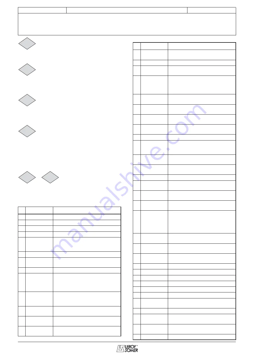
: Trips 0 to 9
Adjustment range: 0 to 102
Contains the last 10 drive trips.
10.20
: Indicates the most recent trip.
10.29
: Indicates the oldest trip.
The possible trips are:
No.
HMI name
Reason for trip
1
DC UnderVolt DC bus undervoltage
2
DC over volt
DC bus overvoltage
3
Over current
Overcurrent at drive output
4
Brak. IGBT
Braking IGBT transistor overcurrent
5
I
IMBALANCED
• Phase current imbalance
• Vectorial sum of 3 motor
currents is non-zero
6
Out Ph. loss
Loss of a motor phase
7
Over speed
The speed is greater than 1.3 times the
value of
00.02
(
01.06
)
9
IGBT U
Problem on an IGBT (U)
10 RECTIFIER Th
Rectifier bridge temperature too high,
there is a ventilation problem, the
ambient temperature is too high or the
load is too great
11
Encoder rot
The measured position does not vary
(the encoder is incorrectly connected,
not powered or the shaft is not turning)
13 UVW reversed
The u, v, w commutation signals of the
encoder are reversed
14 TUNE U Encod
Some encoder signals are present, but
commutation channel U is missing
15 TUNE V Encod
Some encoder signals are present, but
commutation channel V is missing
10.16
10.17
10.18
10.19
10.20
10.29
16
TUNE W
Encod
Some encoder signals are present, but
commutation channel W is missing
18
Autotun.fail
Drive trips during the autotune phase
19
Brak. resist.
Braking resistor overload
I x t :
10.39
= 100%
21
Th IGBT U
• IGBT (U) overheating, ventilation
problem, ambient temperature too
high
• Load too high
24
Motor PTC
Triggering of motor thermal sensor on
ADI3 or MD-Encoder
26
24V over ld
Overload on the +24 V power supply or
digital outputs
27
ADI1 loss
Loss of the current reference on analog
input AI1
28
ADI2 loss
Loss of the current reference on analog
input ADI2
30
COM loss
Loss of serial link communication
31 EEPROM fail.
EEPROM problem or problem with
transfer by XPressKey (key and drive
versions different)
33
Stator res.
Trip during measurement of the stator
resistance
34
Fieldbus loss
Disconnection of the fieldbus during
operation or error
35
Sec. disable
Problem on secure disable input
36
U sign. loss
Loss of encoder commutation
channel U
37
V sign. loss
Loss of encoder commutation
channel V
38
Breakdown
Breakdown of synchronous motor in
sensorless closed loop mode
41
User 1
• User 1 trip triggered
by state 1 of
10.61
.
• In factory settings, overload of the
drive or the braking resistor.
• See
10.17
to
10.19
.
42
User 2
User 2 trip triggered by state 1
of
10.63
.
43
User 3
User 3 trip triggered by state 1
of
10.65
.
44
User 4
User 4 trip triggered by state 1
of
10.67
.
45
User 5
User 5 trip triggered via the serial link.
46
User 6
User 6 trip triggered via the serial link.
47
User 7
User 7 trip triggered via the serial link.
48
User 8
User 8 trip triggered via the serial link.
49
User 9
User 9 trip triggered via the serial link.
50
User 10
User 10 trip triggered via the serial link.
51
PX-I/O
EEPROM
Problem on PX-I/O EEPROM
52 PX-I/O supply Overload of the PX-I/O power supply
53
PX-I/O
CLOCK
Problem on the real-time clock of the
PX-I/O
54
PX-I/O comm
Communication problem between the
drive and the PX-I/O
56
IGBT V
Trip on an IGBT (V)
No.
HMI name
Reason for trip
Содержание POWERDRIVE MD
Страница 4: ...4 COMMISSIONING MANUAL POWERDRIVE MD Variable speed drive LEROY SOMER 3871 en 2011 05 h Notes...
Страница 145: ......


