


112
COMMISSIONING MANUAL
POWERDRIVE MD
Variable speed drive
MENUS AND DIAGRAMS IN ADVANCED SET UP MODE
LEROY-SOMER
3871 en - 2011.05 / h
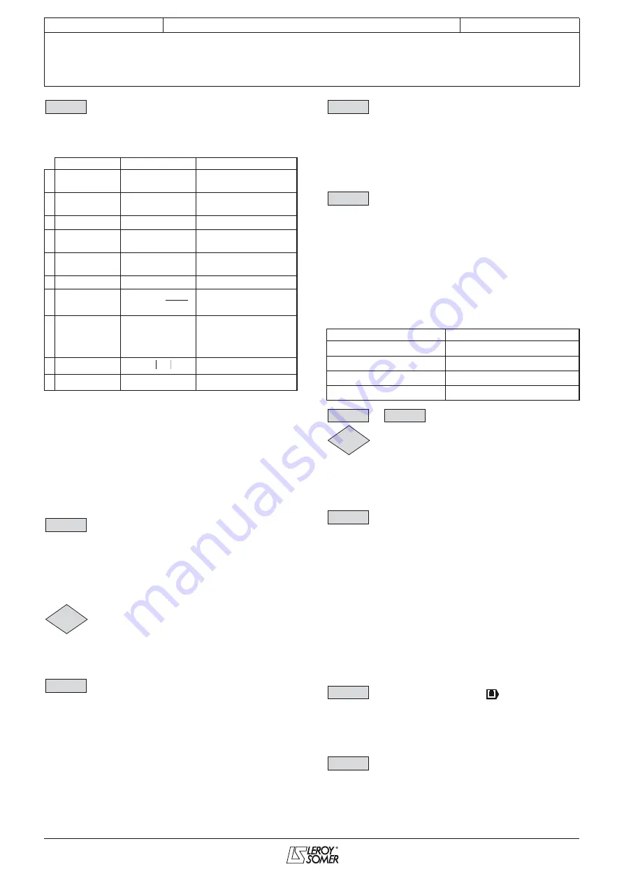
: Function block 2 select
Adjustment range : See table below
Factory setting
: O = V1 (0)
This parameter is used to define the function of the internal
variables processing block.
• If
12.10
or
12.30
is e
q
ual to 2, 3, 4 or 5:
When the result of the calculation is greater than or equal to
32767, the output
12.11
or
12.31
is limited at 32767.
When the result of the calculation is less than or equal to -32768,
the output
12.11
or
12.31
is limited at -32768.
• If
12.10
or
12.30
is e
q
ual to 5:
To avoid a calculation error if V2 = 0, the result of the operation
will be 0.
• If
12.10
or
12.30
is e
q
ual to 9:
To avoid a calculation error, the absolute value of the signal V1
is taken before calculating its square root or cube root.
: Function 2 output destination
Adjustment range :
00.00
to
21.51
Factory setting
:
00.00
This parameter is used to select the destination of the
processed variable.
Any non-protected "non-bit" parameter can be assigned.
If an unsuitable parameter is selected, the value of the variable
taken into account is zero.
: Function block 2 output
Adjustment range : ± 100.00%
Indicates the value of the function output as a percentage of the
adjustment range of the destination parameter.
: Function 2 variable 1 scale
Adjustment range : ± 4.000
Factory setting
: 1.000
Used to scale variable 1 before processing.
CAUTION:
The value at the output of the scalin
g
can only be between
-32767 and +32767. Take this into account accordin
g
to the
adjustment ran
g
e of the source parameter.
: Function 2 variable 2 scale
Adjustment range : ± 4.000
Factory setting
: 1.000
Used to scale variable 2 before processing.
CAUTION:
The value at the output of the scalin
g
can only be between
-32767 and +32767. Take this into account accordin
g
to the
adjustment ran
g
e of the source parameter.
: Function 2 applied factor
Adjustment range : 0 to 100.00
Factory setting
: 0
Depending on its function, the internal variables processing
block may require an associated parameter.
If the block is used to create a first-order filter, the associated
parameter is used as a time constant ; if it is used to generate
a ramp, this parameter is used to adjust the value of the ramp
(in seconds). The ramp time corresponds to the time for
changing from 0 to 100% of the maximum value of the source
parameter.
If the block is used as a power, this parameter is used as
follows:
to
: Not used
: Brake release
Adjustment range : Disabled (0) or Enabled (1)
Indicates the state of the brake control output.
Disabled (0):
The brake is applied.
Enabled (1):
The brake is released.
: Brake controller
Adjustment range : Disabled (0), On contactor (1),
On relay (2), User select (3)
Factory setting
: Disabled (0)
Used to enable brake control and to select to which digital
output it will be assigned.
Disabled (0): Brake control is not enabled.
On contactor (1):
Brake control is enabled. The output is not
assigned automatically, it is up to the user to select the
destination for parameter
12.40
.
On relay (2):
Brake control is enabled. Route the brake control
to the relay by setting
08.28
=
12.40
.
User select (3):
Brake control is enabled. The output is not
assigned automatically; it is up to the user to select the
destination for parameter
12.40
.
: Upper current threshold (
)
Adjustment range : 0 to 200%
Factory setting
: 30%
Used to set the current threshold at which the brake will be
controlled. This current level should provide sufficient torque at
the time the brake is released.
: Lower current threshold
Adjustment range : 0 to 200%
Factory setting
: 10%
Used to set the current threshold below which brake control will
be disabled. It should be set so that loss of the motor power
supply is detected.
HMI name
Output
Comment
0
O = V1
= V1
Used to transfer an
internal variable
1
O = V2
= V2
Used to transfer an
internal variable
2
O=V1+V2
= V1 + V2
Addition of 2 variables
3
O=V1-V2
= V1 - V2
Subtraction of 2
variables
4
=V1xV2/100
= (V1 x V2) ÷ 100
Multiplication of 2
variables
5
=V1/V2x100
= (V1 x 100) ÷ V2 Division of 2 variables
6
=filter/V1
Creation of a first-order
filter
7
O=ramp/V1
= ramped V1
Creation of a linear
ramp.
12.35
is used to
adjust the value of the
ramp
8
O = abs (V1)
=
Absolute value
9 O = V1^
12.35
= V1
12.x5
V1 to the power
12.35
12.30
=
V
1(1 - e )
-t
12.X5
V
1
12.31
12.32
12.33
Function
Associated parameter value
V1
2
2.00
V1
3
3.00
V1
12.00
3
V1
13.00
12.34
12.35
12.36
12.39
12.40
12.41
12.42
12.43
Содержание POWERDRIVE MD
Страница 4: ...4 COMMISSIONING MANUAL POWERDRIVE MD Variable speed drive LEROY SOMER 3871 en 2011 05 h Notes...
Страница 145: ......


