


Commissioning
7
14
MA DrivePLC DE/EN/FR 1.0
Tip!
In the event of faults or errors during commissioning, see chapter ”Troubleshooting and fault
elimination”.
(
16)
Switch-on sequence
1. Before connecting the controller to the supply voltage, check the wiring for completeness and
short-circuit.
2. Switch on the supply voltage for the Drive PLC and the PC.
3. Load the required project into the Drive PLC, using the software “Drive PLC Developer Studio”
(DDS).
(
“Drive PLC Developer Studio - Getting started”, Chapter 4.4
)
4. If you do not want to use the DDS for program control, then you can remove the connection
between the Drive PLC and the PC. Switch off the supply to both instruments before you do this.
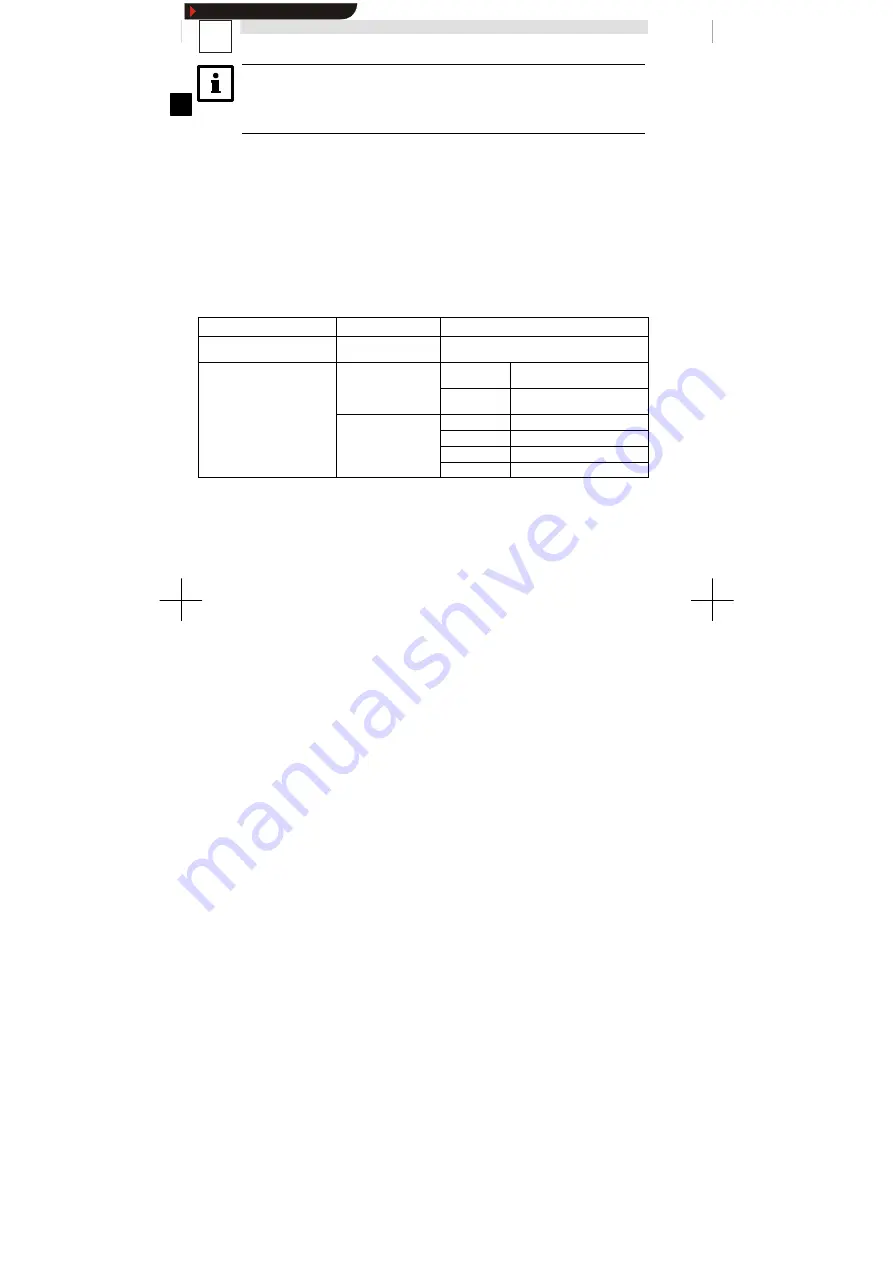
Controlling the program
You have various options for controlling the program in the Drive PLC:
Control through
Program function
Setting/Parameterization
Software Drive PLC Developer
Studio (DDS)
Start, Stop, Reset
Manual DDS - “Getting started”, Chapter 4.4.4
and Chapter 4.4.6
l
Software “Global Drive
Control” (GDC)
Automatic start
C2104 = -0-
*)
Program does not start
automatically after switch-on
Control (GDC)
l
Keypad E822BC
(8200 vector)
C2104 = -1-
Program starts automatically
after switch-on
(8200 vector)
l
Keypad 9371BB (9300)
Start, Stop, Reset
C2108 = -0-
*)
Function executed
Keypad 9371BB (9300)
Start, Stop, Reset
C2108 = -1-
Start program
C2108 = -2-
Stop program
C2108 = -3-
Reset program
*)
Lenze setting
Show/Hide Bookmarks


