


S94P01C -e1
41
6.3.6 Analog Input Scale (velocity scale)
This parameter sets the analog input sensitivity for the velocity reference used
when the drive operates in velocity mode. Units for this parameter are RPM/Volt. To
calculate this value use the following formula:
Vscale = VELOCITYmax / Vin max
VELOCITYmax
maximum desired velocity in RPM
Vin max
max voltage fed to analog input at Velocity
max
Example:
VELOCITYmax = 2000 RPM
Vin max
= 10V
Vscale
= VELOCITYmax / Vin max
= 2000 / 10V
= 200 RPM / Volt (
value to enter
)
6.3.7 ACCEL/DECEL Limits (velocity mode only)
The ACCEL setting determines the time the motor takes to ramp to a higher speed.
The DECEL setting determines the time the motor takes to ramp to a lower speed. If
the ENABLE ACCEL/DECEL LIMITS is set to DISABLE, the drive will automatically
accelerate and decelerate at maximum acceleration limited only by the current limit
established by the PEAK CURRENT LIMIT and CURRENT LIMIT settings.
6.3.8 Reference
The REFERENCE setting selects the reference signal being used by the drive. This
reference signal can be either External or Internal. An External Reference can be one
of three types, an Analog Input signal, a Step and Direction Input or an Input from a
external Master Encoder. The Analog Input reference is used when the drive is either
in torque or velocity mode. The Master Encoder and Step and Direction reference
is used when the drive is in position mode. An Internal Reference is used when the
motion being generated is derived from drive’s internal variable(s), i.e., User Program,
(Refer to the PositionServo Programming Manual).
6.3.9 Step Input Type (position mode only)
This parameter sets the type of input for position reference the drive expects to see.
Signal type can be step and direction (S/D) type or quadrature pulse-train (Master
Encoder / Electronic Gearing). Refer to section 5.2.1 for details on these inputs.
6.3.10 Fault Reset Option
The FAULT RESET OPTION selects the type of action required to reset the drive after
a FAULT signal has been generated by the drive. ON DISABLE clears the fault when
the drive is disabled. This is useful if you have a single drive and motor connected
in a single drive system. The ON ENABLE option clears the fault when the drive is
re-enabled. Choose ON ENABLE if you have a complex servo system with multiple
drives connected to an external controller. This makes troubleshooting easier since
the fault will not be reset until the drive is re-enabled. Thus, a technician can more
easily determine which component of a complex servo system has caused the fault.
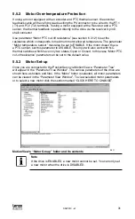
6.3.11 Motor Temperature Sensor
This parameter enables / disables motor over-temperature detection. It must be
disabled if the motor PTC sensor is not wired to either P7.1-2 or to the resolver option
module (P11).
Содержание AC Tech PositionServo 940
Страница 1: ...USERS MANUAL S94P01C e1 S955 ...
Страница 14: ...S94P01C e1 12 3 2 Clearance for Cooling Air Circulation 3 bb 3 bb 3 bb S924 ...
Страница 73: ...S94P01C e1 71 NOTES ...
Страница 74: ...S94P01C e1 72 NOTES ...


