


S94P01C -e1
20
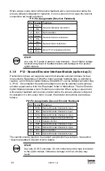
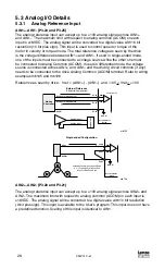
5.1.4 P4 - Motor Feedback / Second Loop Encoder Input
For encoder-based 940 drives, P4 is a 15-pin DB connector that contains connections
for an incremental encoder with Hall emulation tracks or Hall sensors. For
synchronous servo motors, it is necessary to have Hall sensors or Hall emulation
tracks for commutation. If an asynchronous servo motor is used, it is not necessary
to connect Hall sensor inputs. For pin assignments, refer to the table P4A. Encoder
inputs on P4 have 26LS32 or compatible differential receivers for increased noise
immunity. Inputs have all necessary filtering and line balancing components so no
external noise suppression networks are needed.
For resolver-based 941 drives, P4 is a 9-pin DB connector for connecting resolver
feedback and thermal sensor. For pin assignments, refer to the table P4B.
All conductors must be enclosed in one shield and jacket around them. Lenze
recommends that each and every pair (for example, EA+ and EA-) be twisted. In order
to satisfy CE requirements, use of an OEM cable is recommended. Contact your
Lenze representative for assistance.
The PositionServo buffers encoder/resolver feedback from P4 to P3. For example,
when encoder feedback is used, channel A on P4, is Buffered Encoder Output
channel A on P3. For more information on this refer to section 5.2.2 “Buffered Encoder
Outputs”.
STOP!
Use only +5 VDC encoders. Do not connect any other type of encoder
to the PositionServo reference voltage terminals. When using a front-
end controller, it is critical that the +5 VDC supply on the front-end
controller NOT be connected to the PositionServo’s +5 VDC supply, as
this will result in damage to the PositionServo.
Note
• The PositionServo encoder inputs are designed to accept
differentially driven hall signals. Single-ended or open-collector
type hall signals are also acceptable by connecting “HA+”, “HB+”,
“HC+” and leaving “HA-,HB-,HC-” inputs unconnected. You do not
need to supply pull-up resistors for open-collector hall sensors. The
necessary pull-up circuits are already provided.
• Encoder connections (A, B, and Z) must be full differential.
PositionServo doesn’t support single-ended or open-collector type
outputs from the encoder.
• An encoder resolution of 2000 PPR (pre-quadrature) or higher is
recommended.
Using P4 as second encoder input for dual-loop operation.
P4 can be used as a second loop encoder input in situations where the motor is
equipped with a resolver as the primary feedback. If such a motor is used, the drive
must have a resolver feedback option module installed. A second encoder can then be
connected to the A and B lines of the P4 connector for dual loop operation. See “Dual
loop feedback operation” for details (Section 8.4).
Содержание AC Tech PositionServo 940
Страница 1: ...USERS MANUAL S94P01C e1 S955 ...
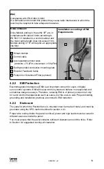
Страница 14: ...S94P01C e1 12 3 2 Clearance for Cooling Air Circulation 3 bb 3 bb 3 bb S924 ...
Страница 73: ...S94P01C e1 71 NOTES ...
Страница 74: ...S94P01C e1 72 NOTES ...


