


S94P01C -e1
34
Note
If there was a problem with the motor connection, hall sensor
connection or resolver connection, MotionView will respond with an
error message. Common problems are with power, shield and ground
terminations or an improper cable is being used.
Correct the wiring problem(s) and repeat steps 1 - 6.
If the error message repeats, exchange motor phases U and V
(R and S) and repeat. If problems persist, contact the factory.
7. If autophasing is completed with no error then MotionView will return to the
motor dialog box. For motors with incremental encoders, the parameter field
“Hall order” and the check boxes “inverted”, “B leads A for CW” will be filled
in with correct values. For resolver equipped motors, fields “Offset ” and “CW
for positive” will be correctly set.
8. Click “Save File” to save the completed motor file (you can use the same
filename as you use to save initial data in step 1) and click OK to load the
motor data to the drive.
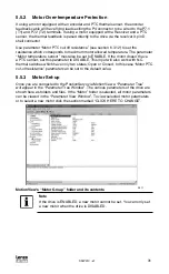
5.6.3 Custom Motor Data Entry
A Custom Motor file is created by entering motor data into the “Motor Parameters”
dialog box. This box is divided up into the following three sections, or frames:
Electrical constants
Mechanical constants
Feedback
When creating a custom motor you must supply all parameters listed in these
sections. All entries are mandatory except the motor inertia (Jm) parameter. A value of
0 may be entered for the motor inertia if the actual value is unknown.
5.6.3.1 Electrical constants
Motor Torque Constant (Kt).
Enter the value and select proper units from the drop-down list.
Note
Round the calculated result to 3 significant places.
Motor Voltage Constant (Ke).
The program expects Ke to be entered as a phase-to-phase Peak voltage. If you have
Ke as an RMS value, multiply this value by 1.414 for the correct Ke Peak value.
Phase-to-phase winding Resistance (R) in Ohms.
This is also listed as the terminal resistance (Rt). The phase-to-phase winding
Resistance (R) will typically be between 0.05 and 200 Ohms.
Phase-to-phase winding Inductance (L).
This must be set in millihenries (mH). The phase-to-phase winding Inductance (L) will
typically be between 0.1 and 200.0 mH.
Note
If the units for the phase-to-phase winding Inductance (L) are given in
micro-henries (µH), then divide by 1000 to get mH.
Содержание AC Tech PositionServo 940
Страница 1: ...USERS MANUAL S94P01C e1 S955 ...
Страница 14: ...S94P01C e1 12 3 2 Clearance for Cooling Air Circulation 3 bb 3 bb 3 bb S924 ...
Страница 73: ...S94P01C e1 71 NOTES ...
Страница 74: ...S94P01C e1 72 NOTES ...


