background image

To replace the system board, do the following:

1. Remove all media from the drives and turn off all attached devices and the server. Then, disconnect all

power cords from electrical outlets and disconnect all cables that are connected to the server.

2. Remove the server cover. See “Removing the server cover” on page 41.

3. Lay the server on its side for easier access to the system board.

4. Remove all memory modules and PCI cards that are currently installed. See “Installing or removing a

memory module” on page 45 and “Installing or replacing a PCI card” on page 62.

5. Remove the heat sink and fan assembly from the failing system board. See “Replacing the heat sink and

fan assembly” on page 77.

Note:

Place the heat sink and fan assembly on its side so that the thermal grease on the bottom of it

does not get in contact with anything.

6. Remove the microprocessor from the failing system board. See “Replacing the microprocessor” on

page 83.

7. Remove the battery from the failing system board. See “Replacing the system board battery” on page 86.

8. Note the location of all cable connections on the system board and disconnect all cables. See “Locating

parts on the system board” on page 17.

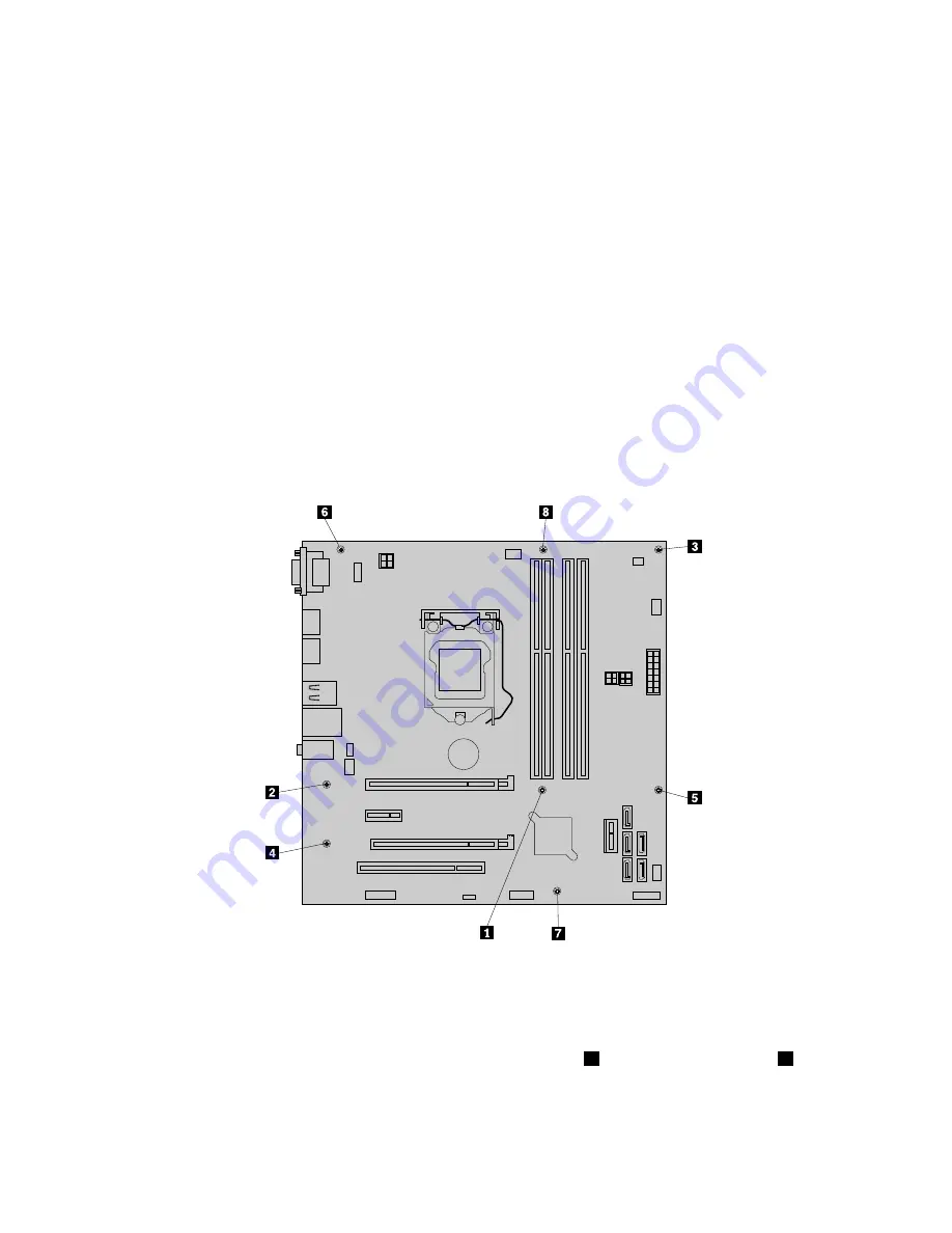
9. Remove the eight screws that secure the system board to the chassis by following the sequence shown

in the following illustration.

10. Carefully lift the failing system board out of the chassis.

11. Remove the retention module from the bottom of the failing system board and then install it to the

new system board.

12. Position the new system board into the chassis so that the screw holes in the new system board are

aligned with those in the chassis. Install the eight screws that secure the system board to the chassis in
the reverse order that they were removed; that is, install the screw

8

first and install the screw

1

last.

13. Remove the microprocessor socket cover from the new system board.

14. Install the memory modules, PCI cards, battery, microprocessor, and heat sink and fan assembly that

you removed from the failing system board to the new system board.

88

ThinkServer TS140 Hardware Maintenance Manual

Содержание ThinkServer TS140

Страница 1: ...ThinkServer TS140 Hardware Maintenance Manual Machine Types 70A0 70A1 70A4 and 70A5 ...

Страница 2: ...r product Safety information on page iii Appendix A Notices on page 103 Fifth Edition October 2014 Copyright Lenovo 2013 2014 LIMITED AND RESTRICTED RIGHTS NOTICE If data or software is delivered pursuant a General Services Administration GSA contract use reproduction or disclosure is subject to restrictions set forth in Contract No GS 35F 05925 ...

Страница 3: ...tup program 32 Using the ThinkServer EasyStartup program on a Windows operating system 33 Configuring RAID 34 About RAID 34 Configuring the system BIOS to enable onboard SATA RAID functionality 35 Creating RAID volumes 35 Deleting RAID volumes 36 Resetting disks to non RAID 36 Updating the firmware 36 Using the Firmware Updater program 37 Chapter 6 Installing removing or replacing hardware 39 Guid...

Страница 4: ... Lenovo Support Web site 99 Help and service 100 Before you call 100 Calling for service 100 Using other services 101 Purchasing additional services 101 Appendix A Notices 103 Trademarks 104 Important notes 104 Particulate contamination 104 Polyvinyl Chloride PVC cable and cord notice 105 Recycling information 105 Battery return program 105 Battery recycling information for Taiwan 106 Requirements...

Страница 5: ...n käyttöä Avant d utiliser le produit veillez à bien lire et comprendre les instructions de sécurité multilingues figurant sur le DVD de documentation fourni avec le produit Πριν χρησιμοποιήσετε το προϊόν βεβαιωθείτε ότι έχετε διαβάσει και κατανοήσει τις οδηγίες ασφάλειας οι οποίες είναι διαθέσιμες σε διάφορες γλώσσες στο DVD τεκμηρίωσης που συνοδεύει το προϊόν Vor Verwendung des Produkts sollten ...

Страница 6: ... dodanom s produktom Preden začnete uporabljati izdelek je pomembno da preberete in razumete večjezična varnostna navodila na DVD ju z dokumentacijo ki ste ga prejeli skupaj z izdelkom Antes de utilizar el producto asegúrese de leer y comprender las instrucciones de seguridad multilingües del DVD de documentación que se proporciona con el producto Var noga med att läsa säkerhetsinstruktionerna på ...

Страница 7: ... instructed otherwise in the installation and configuration procedures Connect and disconnect cables as described in the following table when installing moving or opening covers on this product or attached devices To connect To disconnect 1 Turn everything OFF 2 First attach all cables to devices 3 Attach signal cables to connectors 4 Attach power cords to outlets 5 Turn devices ON 1 Turn everythi...

Страница 8: ...A or Class 3B laser diode Note the following Laser radiation when open Do not stare into the beam do not view directly with optical instruments and avoid direct exposure to the beam Statement 4 18 kg 39 7 lb 32 kg 70 5 lb 55 kg 121 2 lb 32 kg 70 5 lb 55 kg 121 2 lb 100 kg 220 5 lb CAUTION Use safe practices when lifting Statement 5 CAUTION The power control button on the device and the power switc...

Страница 9: ...s will not support the weight of the device Statement 8 CAUTION Never remove the cover on a power supply or any part that has the following label attached Hazardous voltage current and energy levels are present inside any component that has this label attached There are no serviceable parts inside these components If you suspect a problem with one of these parts contact a service technician Statem...

Страница 10: ...s extended on the rails Statement 14 CAUTION Some accessory or option board outputs exceed Class 2 or limited power source limits You must install the appropriate interconnecting cabling in accordance with your local electrical code requirements Statement 15 CAUTION The power control button on the device may put the device in standby mode instead of turning off the device In addition the device mi...

Страница 11: ... V direct current The branch circuit overcurrent protection must be rated in accordance with local electrical code requirements Use 1 3 mm2 or 16 American Wire Gauge AWG copper conductor only not exceeding 3 meters in length Torque the wiring terminal screws to 1 4 newton meters or 12 inch pounds Provide a readily available approved and rated disconnect device in the field wiring Statement 17 CAUT...

Страница 12: ...e apparent hazard could be and whether you can continue without first correcting the problem Consider these conditions and the safety hazards they present Electrical hazards especially primary power primary voltage on the frame can cause serious or fatal electrical shock Explosive hazards such as a damaged Cathode Ray Tube CRT monitor or a bulging capacitor Mechanical hazards such as loose or miss...

Страница 13: ...worn frayed or pinched cables 9 Check that the power supply cover fasteners screws or rivets have not been removed or tampered with Grounding requirements Electrical grounding of the server is required for operator safety and correct system function Proper grounding of the electrical outlet can be verified by a certified electrician Copyright Lenovo 2013 2014 xi ...

Страница 14: ...xii ThinkServer TS140 Hardware Maintenance Manual ...

Страница 15: ...tp www lenovo com warranty llw_02 If you cannot obtain the LLW through the documentation DVD or Lenovo Web site contact your local Lenovo office or reseller to obtain a printed version of the LLW free of charge For warranty service consult the worldwide Lenovo Support telephone list Telephone numbers are subject to change without notice The most up to date telephone list for Lenovo Support is alwa...

Страница 16: ...cumentation DVD that comes with your server before using the product This document also provides information about how to find the most up to date information on the Lenovo Support Web site Documentation DVD The documentation DVD which comes with your server contains various documents for your server in Portable Document Format PDF and HyperText Markup Language HTML The documentation DVD is not bo...

Страница 17: ...document includes the terms and conditions of the Lenovo License Agreement User Guide This document provides detailed information to help you get familiar with your server and help you use configure and maintain your server Document only for trained service personnel The following document is intended only for trained service personnel of Lenovo Hardware Maintenance Manual This document provides i...

Страница 18: ...4 ThinkServer TS140 Hardware Maintenance Manual ...

Страница 19: ...ernet cable and power cords to the server See Rear view of the server on page 14 to locate the connectors 4 Turn on the server to verify operation See Turning on the server on page 21 5 Review the Unified Extensible Firmware Interface UEFI settings and customize as needed See Starting the Setup Utility program on page 23 6 Configure RAID and install the operating system and basic drivers See Think...

Страница 20: ...6 ThinkServer TS140 Hardware Maintenance Manual ...

Страница 21: ...including printed documentation a documentation DVD and software media Features This topic provides general information about the server features for various models Depending on your specific model some features might vary or not be available For information about your specific model use the Setup Utility program See Viewing information in the Setup Utility program on page 23 You also can refer to...

Страница 22: ...ses to read and store data The internal drives supported by your server vary by model Hard disk drive Up to four 3 5 inch Serial Advanced Technology Attachment SATA hard disk drives Up to four 2 5 inch SATA hard disk drives or solid state drives Optical drive One SATA optical drive in some models RDX drive Your server supports an internal RDX drive that enables you to store data on RDX media The i...

Страница 23: ...s RAS are three important server design features The RAS features help you to ensure the integrity of the data stored on the server the availability of the server when you need it and the ease with which you can diagnose and correct problems Your server has the following RAS features Security features Administrator password and user password to help protect unauthorized access to the server see Us...

Страница 24: ...n about the software programs see Software on page 11 Wake on LAN When the Wake on LAN feature is enabled on a computer that is connected to a LAN a network administrator can remotely turn on or wake up the computer from a management console using remote network management software Besides many other functions such as data transfer and software updates can be performed remotely without remote atte...

Страница 25: ...ith package 8 to 90 non condensing Electrical input Universal input Low range Minimum 100 V ac Maximum 127 V ac Input frequency range 50 to 60 Hz High range Minimum 200 V ac Maximum 240 V ac Input frequency range 50 to 60 Hz Software This topic provides information about the software programs that you can use to set up use and maintain the server ThinkServer EasyStartup The ThinkServer EasyStartup...

Страница 26: ...ng the firmware on page 36 and Updating or recovering the BIOS on page 29 RAID configuration utilities Your server supports onboard SATA software Redundant Array of Independent Disks RAID For detailed information see Configuring RAID on page 34 Diagnostic programs The following diagnostic programs are available for you to diagnose server problems ThinkServer Diagnostic Tool ThinkServer System Prof...

Страница 27: ...achine type model and serial number label Figure 2 Machine type model and serial number label Front view of the server This topic provides information to help you locate the parts on the front of the server Chapter 3 Product overview 13 ...

Страница 28: ... Rear view of the server This topic provides information to help you locate the connectors and components on the rear of your server Figure 4 Rear connector locations on page 15 shows the locations of the connectors on the rear of your server Some connectors on the rear of your server are color coded to help you determine where to connect the cables on your server 14 ThinkServer TS140 Hardware Mai...

Страница 29: ...tor of the server Audio line out connector Used to send audio signals from the server to external devices such as powered stereo speakers speakers with built in amplifiers headphones multimedia keyboards or the audio line in connector on a stereo system or other external recording device DisplayPort connector Used to attach a high performance monitor a direct drive monitor or other devices that us...

Страница 30: ...e a Category 5 Ethernet cable Figure 5 Ethernet status LEDs Ethernet status LED Color Status Description Amber On The connection speed is 1000 Mbps Green On The connection speed is 100 Mbps 1 Left data speed None Off The connection speed is 10 Mbps Yellow On The server is connected to a LAN None Off The server is disconnected from a LAN 2 Right link and activity Yellow Blinking The LAN is connecte...

Страница 31: ...he USB connectors on the front of the server 5 Microprocessor fan connector 18 Front USB 2 0 connector for connecting an additional USB device 6 Memory slot 1 DIMM1 19 Clear CMOS Complementary Metal Oxide Semiconductor Recovery jumper 7 Memory slot 2 DIMM2 20 Serial COM2 connector 8 Memory slot 3 DIMM3 21 PCI card slot 9 Memory slot 4 DIMM4 22 PCI Express x4 card slot 10 Thermal sensor connector 2...

Страница 32: ...bly 2 Microprocessor 8 Hard disk drive 3 Memory module 9 System board 4 Optical drive 10 Graphics card available in some models 5 Card reader drive bay 11 Rear fan assembly 6 Front bezel 12 Power supply assembly Internal drives Internal drives are devices that your server uses to read and store data You can add drives to your server to increase storage capacity and enable your server to read other...

Страница 33: ...re 8 Drive bay locations 1 Primary optical drive bay also can be used to install the fourth hard disk drive 2 Secondary optical drive bay also can be used to install a tertiary hard disk drive 3 Secondary hard disk drive bay 4 Primary hard disk drive bay Chapter 3 Product overview 19 ...

Страница 34: ...20 ThinkServer TS140 Hardware Maintenance Manual ...

Страница 35: ...witch on the power supply do not turn off the electrical current supplied to the device The device also might have more than one power cord To remove all electrical current from the device ensure that all power cords are disconnected from the power source The server can be turned off in any of the following ways You can turn off the server from the operating system if your operating system support...

Страница 36: ...22 ThinkServer TS140 Hardware Maintenance Manual ...

Страница 37: ...ram For password information see Using passwords on page 27 Viewing information in the Setup Utility program The Setup Utility program menu lists various items about the system configuration Select a desired item to view information or change settings When working with the Setup Utility program you must use the keyboard The keys used to perform various tasks are displayed on the right bottom pane ...

Страница 38: ...can download the BIOS update utility to update the BIOS if the newer BIOS version specifically solves a problem you have See Updating or recovering the BIOS on page 29 If the power to your server is interrupted while the BIOS is being updated and your server cannot start correctly use the BIOS recovery switch to recover from a BIOS update failure See Recovering from a BIOS update failure on page 3...

Страница 39: ...ipset CRID Support Enable or disable the Chipset CRID Support feature Security menu You can set passwords and configure other security features on the Security menu in the Setup Utility program For each menu item press Enter to show selectable options and select a desired option by using the up and down arrow keys or type desired values from the keyboard Some items are displayed on the menu only i...

Страница 40: ...9 The Startup menu contains various configuration submenus and items For each submenu and item press Enter to show selectable options and select a desired option by using the up and down arrow keys or type desired values from the keyboard Some items are displayed on the menu only if the server supports the corresponding features The Startup menu contains the following submenus Primary Boot Sequenc...

Страница 41: ... program do the following 1 Start the Setup Utility program See Starting the Setup Utility program on page 23 2 On the Main menu select System Time Date 3 Use the Tab key to switch between data elements and type the numbers from the keyboard to set the system date and time 4 Press F10 to save settings and exit the Setup Utility program Using passwords By using the Setup Utility program you can set...

Страница 42: ...e A password can be any combination of up to 64 alphabetic and numeric characters For more information see Password considerations on page 27 Erasing lost or forgotten passwords clearing CMOS This topic provides instructions on how to erase lost or forgotten passwords such as a user password To erase a lost or forgotten password do the following 1 Remove all media from the drives and turn off all ...

Страница 43: ...r to select the device of your choice Then the server will start up from the selected device To view or permanently change the configured startup device sequence do the following 1 Start the Setup Utility program See Starting the Setup Utility program on page 23 2 On the Startup menu select the devices for the Primary Startup Sequence the Automatic Startup Sequence and the Error Startup Sequence R...

Страница 44: ...e procedure in an environment with a steady power supply Besides ensure that your server can restart successfully without encountering hardware problems If you have updated the BIOS firmware all the BIOS settings become the default settings of the updated BIOS version You need to check and reconfigure the BIOS settings for your specific needs You also can record your specific BIOS settings before ...

Страница 45: ...ng supported operating systems and device drivers on your server The program works in conjunction with your Windows or Linux operating system installation disc to automate the process of installing the operating system and associated device drivers This program is provided with your server on a self starting bootable ThinkServer EasyStartup DVD The user guide for the program also is on the DVD and...

Страница 46: ...ght be English only In this case the keyboard layout should be English 3 After selecting the language and keyboard layout click OK Then you will see one or more messages about configuring storage devices Click Next until you are presented with the Lenovo License Agreement Read the Lenovo License Agreement carefully In order to continue you must accept the terms by clicking Agree Then the Date and ...

Страница 47: ...em You can run the ThinkServer EasyStartup DVD on a Windows operating system with the Internet Explorer 6 0 Web browser or a later version installed Enter the operating system and insert the ThinkServer EasyStartup DVD into an internal or external optical drive The DVD starts automatically in most environments If the DVD does not start automatically open the launch exe file located in the root dir...

Страница 48: ...lity and fault tolerance compared to single drive storage systems Data loss resulting from a drive failure can be prevented by reconstructing missing data from the remaining drives The following list describes some of the most commonly used RAID levels RAID 0 block level striping without parity or mirroring Simple stripe sets are normally referred to as RAID 0 RAID 0 uses striping to provide high ...

Страница 49: ...of four hard disk drives and also requires an even number of drives for example six hard disk drives or eight hard disk drives Configuring the system BIOS to enable onboard SATA RAID functionality This describes how to configure the system BIOS to enable onboard SATA RAID functionality Note Use the arrow keys on the keyboard to make selections To enable SATA RAID functionality do the following 1 S...

Страница 50: ...tility during system startup 2 Use the up and down arrow keys to select Reset Disks to Non RAID and press Enter 3 Use the arrow keys and the space key to mark individual physical hard disk drives to be reset and then press Enter to complete the selection 4 When prompted press Y to confirm the reset action 5 After resetting the hard disk drives to non RAID you can See Deleting RAID volumes on page ...

Страница 51: ...n restart successfully without encountering hardware problems 1 Go to http www lenovo com drivers and follow the instructions on the Web page to locate the Firmware Updater program 2 Download the ISO image for the Firmware Updater program and the TXT file that contains installation instructions 3 Use any CD or DVD burning software to create a bootable disc with the ISO image 4 Print the TXT file a...

Страница 52: ...38 ThinkServer TS140 Hardware Maintenance Manual ...

Страница 53: ...ur server go to http www lenovo com drivers and then follow the instructions on the Web page See Updating the firmware on page 36 for more information Before you install optional hardware devices ensure that the server is working correctly If the server is not working correctly see Chapter 7 Troubleshooting and diagnostics on page 93 to do basic troubleshooting If the problem cannot be solved see ...

Страница 54: ... can cause static electricity to build up around you Always carefully handle the parts and other components such as PCI Express cards memory modules system boards and microprocessors by edges or frame Do not touch solder joints pins or exposed circuitry Do not leave the device where others can handle and possibly damage the device Before you replace a new part touch the static protective package c...

Страница 55: ...le the server is running Operating the server without the air ducts or air baffles might cause the microprocessor s to overheat For servers that support up to two microprocessors ensure that the second microprocessor socket always contains a microprocessor or is protected by a microprocessor socket cover Working inside the server with the power on Attention Static electricity that is released to i...

Страница 56: ...cures the server cover such as a padlock or an integrated cable lock See Integrated cable lock on page 92and Padlock on page 92 5 Remove the two thumbscrews that secure the server cover 6 Press the cover release button on the side of the server and slide the cover to the rear of the server to remove the cover Figure 9 Removing the server cover Removing and reinstalling the front bezel Attention Do...

Страница 57: ...tlets and disconnect all cables that are connected to the server 2 Remove the server cover See Removing the server cover on page 41 3 Remove the front bezel by releasing the three plastic tabs on the left side and pivoting the front bezel outward Figure 10 Removing the front bezel Chapter 6 Installing removing or replacing hardware 43 ...

Страница 58: ...failing hardware devices If you are handling a server option refer to the appropriate installation or removal instructions in this topic along with the instructions that come with the option Notes Use only parts provided by Lenovo Depending on the model your server might look slightly different from the illustrations in this topic The EMI integrity and cooling of the server are protected by having...

Страница 59: ...open documents and exit all applications 2 Insert the ThinkServer EasyStartup DVD that came with your server into the DVD drive Note You do not need to use the driver disc that came with the Ethernet card 3 Right click My Computer and select Properties The System Properties window opens 4 On the Hardware tab click the Device Manager button The Device Manager window opens 5 Expand Network adapters ...

Страница 60: ...emory slots on the system board Figure 12 Memory slots on the system board 1 Memory slot DIMM1 3 Memory slot DIMM3 2 Memory slot DIMM2 4 Memory slot DIMM4 The following table explains the memory module installation rules for your server The X mark indicates the memory slots into which the memory modules should be installed in different situations Note The installed memory modules must be the same ...

Страница 61: ...ds from electrical outlets and disconnect all cables that are connected to the server 2 Remove the server cover See Removing the server cover on page 41 3 Lay the server on its side for easier operation 4 Locate the memory slots on the system board See Locating parts on the system board on page 17 5 Remove any parts or disconnect any cables that might prevent your access to the memory slots Depend...

Страница 62: ...tempt any repair before reading and understanding Safety information on page iii and Guidelines on page 39 This topic provides instructions on how to remove a memory module Before you begin print all the related instructions or ensure that you can view the PDF version on another computer for reference Note To optimize system performance make sure that you consider and follow the memory module inst...

Страница 63: ...section To complete the removal procedure go to Completing the parts replacement on page 90 Installing the 2 5 inch solid state drive or hard disk drive Attention Do not open your server or attempt any repair before reading and understanding Safety information on page iii and Guidelines on page 39 This topic provides instructions on how to install the 2 5 inch solid state drive or hard disk drive ...

Страница 64: ...stall the 2 5 inch drive with the drive adapter into the 3 5 inch hard disk drive bracket flex the bracket and align pin 1 pin 2 pin 3 and pin 4 on the bracket with the corresponding holes in the drive adapter Figure 17 Installing the 2 5 inch drive with the drive adapter into the hard disk drive bracket 3 Connect the signal cable and the power cable to the 2 5 inch drive 50 ThinkServer TS140 Hard...

Страница 65: ...k drive or solid state drive install the drive into a 3 5 inch to 2 5 inch drive adapter first See Installing the 2 5 inch solid state drive or hard disk drive on page 49 Installing the tertiary hard disk drive Attention Do not open your server or attempt any repair before reading and understanding Safety information on page iii and Guidelines on page 39 You can install a tertiary 3 5 inch hard di...

Страница 66: ...ket from a local computer retailer or by contacting the Customer Support Center Figure 18 Installing the hard disk drive into the drive conversion bracket 5 Install the retainer on the side of the bracket Figure 19 Installing the retainer on the side of the bracket 6 If there is a metal static shield installed in the secondary optical drive bay remove the metal static shield 52 ThinkServer TS140 H...

Страница 67: ...the bracket snaps into position Figure 20 Installing the drive conversion bracket into the secondary optical drive bay 8 Connect the signal cable and the power cable to the rear of the new hard disk drive Figure 21 Connecting cables to the hard disk drive Chapter 6 Installing removing or replacing hardware 53 ...

Страница 68: ...y hard disk drive Attention Do not open your server or attempt any repair before reading and understanding Safety information on page iii and Guidelines on page 39 This topic provides instructions on how to remove the tertiary 3 5 inch hard disk drive To remove the tertiary 3 5 inch hard disk drive do the following 1 Remove all media from the drives and turn off all attached devices and the server...

Страница 69: ...t of the server Figure 23 Removing the drive conversion bracket 7 Remove the four screws that secure the hard disk drive Then remove the hard disk drive out of the drive conversion bracket Figure 24 Removing the hard disk drive out of the drive conversion bracket Chapter 6 Installing removing or replacing hardware 55 ...

Страница 70: ...rmation on page iii and Guidelines on page 39 You can install a slim optical drive and a fourth hard disk drive into the optical drive bay of your server This topic provides instructions on how to install the slim optical drive and the fourth hard disk drive into the optical drive bay To install the slim optical drive and the fourth hard disk drive do the following 1 Remove all media from the driv...

Страница 71: ...e retainer 6 Install the slim optical drive with the retainer into the cage Figure 27 Installing the slim optical drive into the cage 7 Press the tab at the front of the cage until you hear a click The slim optical drive is secured in place Figure 28 Securing the slim optical drive in the cage Chapter 6 Installing removing or replacing hardware 57 ...

Страница 72: ...drive into the cage 9 Install the four screws to secure the hard disk drive in the cage Figure 30 Installing the screws to secure the hard disk drive in the cage 10 Install the cage retainer on the side of the cage Figure 31 Installing the cage retainer 58 ThinkServer TS140 Hardware Maintenance Manual ...

Страница 73: ...ard See Locating parts on the system board on page 17 Note If your server has a tertiary hard disk drive installed the fan power converter cable connector 2 is connected to the hard disk drive fan connector on the system board Connect the cable of the fan for the fourth hard disk drive to one of the available connectors 1 of the fan power converter cable Figure 33 Connecting the cable of the fan f...

Страница 74: ...t all cables that are connected to the server 2 Remove the server cover See Removing the server cover on page 41 3 Remove the front bezel See Removing and reinstalling the front bezel on page 42 4 Disconnect the signal cables and the power cables from the slim optical drive and the fourth hard disk drive 5 Disconnect the cable of the fan for the fourth hard disk drive from the hard disk drive fan ...

Страница 75: ...emoving the slim optical drive from the cage 8 Remove the slim optical drive retainer by removing the two screws that secure the retainer Figure 36 Removing the slim optical drive retainer 9 Remove the four screws that secure the hard disk drive Then slide the hard disk drive out of the rear of the cage Chapter 6 Installing removing or replacing hardware 61 ...

Страница 76: ...r before reading and understanding Safety information on page iii and Guidelines on page 39 This topic provides instructions on how to install or replace a PCI card Your server has one standard PCI card slot one PCI Express x1 card slot one PCI Express x4 card slot and one PCI Express x16 card slot To install or replace a PCI card do the following 1 Remove all media from the drives and turn off al...

Страница 77: ...3 At the rear of the server press the release button 1 to open the PCI card latch 2 Figure 38 Opening the PCI card latch Chapter 6 Installing removing or replacing hardware 63 ...

Страница 78: ... is held in place by a retaining clip open the card retaining clip 1 as shown Grasp the PCI card and gently pull it out of the card slot Figure 39 Opening the PCI card retaining clip Figure 40 Removing a PCI card 5 Remove the new PCI card from its static protective package 6 Install the new PCI card into the appropriate slot on the system board See Locating parts on the system board on page 17 Not...

Страница 79: ...ard Note If you are installing a PCI card into a slot with the retaining clip close the card retaining clip as shown Figure 42 Closing the PCI card retaining clip What to do next To work with another piece of hardware go to the appropriate section Chapter 6 Installing removing or replacing hardware 65 ...

Страница 80: ...re connected to the server 2 Remove the server cover See Removing the server cover on page 41 3 Remove the front bezel See Removing and reinstalling the front bezel on page 42 4 Depending on whether you are installing or replacing an optical drive do one of the following If you are installing a secondary optical drive remove the plastic panel in the front bezel for the drive bay you want to use If...

Страница 81: ...em board See Locating parts on the system board on page 17 Then locate an available five wire power connector and connect it to the SATA drive Figure 45 Connecting a SATA optical drive What to do next To work with another piece of hardware go to the appropriate section To complete the installation or replacement go to Completing the parts replacement on page 90 Installing or replacing an internal ...

Страница 82: ...that are connected to the server 2 Remove the server cover See Removing the server cover on page 41 3 Remove the front bezel See Removing and reinstalling the front bezel on page 42 4 Locate the drive bay where you want to install or replace the RDX drive See Internal drives on page 18 5 Depending on whether you are installing or replacing the RDX drive do one of the following If you are installin...

Страница 83: ...n the system board See Locating parts on the system board on page 17 Figure 48 Connecting the RDX drive 8 Reinstall the front bezel See Removing and reinstalling the front bezel on page 42 9 Do one of the following If you are installing an RDX drive save the removed plastic panel from the front bezel in the event that you later remove the drive and need the plastic panel to cover the drive bay If ...

Страница 84: ...nnect all power cords from electrical outlets and disconnect all cables that are connected to the server 2 Remove the server cover See Removing the server cover on page 41 3 Locate the secondary hard disk drive See Locating parts on the system board on page 17 and Internal drives on page 18 4 If you are replacing the secondary hard disk drive disconnect the signal cable and the power cable from th...

Страница 85: ...ard disk drive into the bracket 8 Slide the new hard disk drive into the hard disk drive cage until it snaps into position Figure 51 Installing the secondary hard disk drive Chapter 6 Installing removing or replacing hardware 71 ...

Страница 86: ... hard disk drive Note For a 2 5 inch hard disk drive or solid state drive install the drive into a 3 5 inch to 2 5 inch drive adapter first See Installing the 2 5 inch solid state drive or hard disk drive on page 49 To replace the primary hard disk drive do the following 1 Remove all media from the drives and turn off all attached devices and the server Then disconnect all power cords from electri...

Страница 87: ...hard disk drive into the blue bracket flex the sides of the bracket and align pin 1 pin 2 pin 3 and pin 4 on the bracket with the corresponding holes in the hard disk drive Do not touch the circuit board 5 on the bottom of the hard disk drive Figure 54 Installing the hard disk drive into the bracket 8 Slide the new hard disk drive into the drive cage until it snaps into position Chapter 6 Installi...

Страница 88: ...e go to the appropriate section To complete the replacement go to Completing the parts replacement on page 90 Replacing the power supply assembly Attention Do not open your server or attempt any repair before reading and understanding Safety information on page iii and Guidelines on page 39 This topic provides instructions on how to replace the power supply assembly Although there are no moving pa...

Страница 89: ...parts contact a service technician To replace the power supply assembly do the following 1 Remove all media from the drives and turn off all attached devices and the server Then disconnect all power cords from electrical outlets and disconnect all cables that are connected to the server 2 Remove the server cover See Removing the server cover on page 41 3 Lay the server on its side and disconnect t...

Страница 90: ...supply assembly is the correct replacement 7 Install the new power supply assembly into the chassis so that the screw holes in the power supply assembly align with those in the chassis 8 Install and tighten the four screws to secure the power supply assembly Note Use only screws provided by Lenovo 9 Reconnect the power supply assembly cables to the system board and each of the drives 10 Secure the...

Страница 91: ... removing the server cover To replace the heat sink and fan assembly do the following 1 Remove all media from the drives and turn off all attached devices and the server Then disconnect all power cords from electrical outlets and disconnect all cables that are connected to the server 2 Remove the server cover See Removing the server cover on page 41 3 Lay the server on its side for easier access t...

Страница 92: ...nk and fan assembly on the system board so that the four screws on the heat sink and fan assembly are aligned with the corresponding holes on the system board Make sure that you properly place the heat sink and fan assembly so that you can easily connect the heat sink and fan assembly cable to the microprocessor fan connector on the system board 9 Follow this sequence to install the four screws to...

Страница 93: ... the front bezel on page 42 4 Disconnect the front audio and USB assembly cable from the system board See Locations on page 12 5 Note the front audio and USB assembly cable routing and remove the screw that secures the front audio and USB assembly Then remove the front audio and USB assembly from the chassis Figure 60 Removing the front audio and USB assembly 6 Route the new front audio and USB as...

Страница 94: ...tlets and disconnect all cables that are connected to the server 2 Remove the server cover See Removing the server cover on page 41 3 Remove the front bezel See Removing and reinstalling the front bezel on page 42 4 Disconnect the front fan assembly cable from the power fan connector on the system board See Locating parts on the system board on page 17 5 The front fan assembly is attached to the c...

Страница 95: ...fore reading and understanding Safety information on page iii and Guidelines on page 39 This topic provides instructions on how to replace the rear fan assembly To replace the rear fan assembly do the following 1 Remove all media from the drives and turn off all attached devices and the server Then disconnect all power cords from electrical outlets and disconnect all cables that are connected to t...

Страница 96: ...ear fan assembly out of the chassis Note The new rear fan assembly will have four new rubber mounts attached Figure 63 Removing the rear fan assembly 6 Install the new rear fan assembly by aligning the new rubber mounts with the corresponding holes in the chassis and push the rubber mounts through the holes 82 ThinkServer TS140 Hardware Maintenance Manual ...

Страница 97: ...te the replacement go to Completing the parts replacement on page 90 Replacing the microprocessor Attention Do not open your server or attempt any repair before reading and understanding Safety information on page iii and Guidelines on page 39 This topic provides instructions on how to replace the microprocessor CAUTION The heat sink and microprocessor might be very hot Turn off the server and wai...

Страница 98: ...cted to the system board See Locating parts on the system board on page 17 5 Remove the heat sink and fan assembly See Replacing the heat sink and fan assembly on page 77 Note Place the heat sink and fan assembly on its side so that the thermal grease on the bottom of it does not get in contact with anything 6 Lift the small handle 1 and open the retainer 2 to access the microprocessor 3 Figure 65...

Страница 99: ...t the small handle is in the raised position and the microprocessor retainer is fully open 9 Remove the protective cover that protects the gold contacts of the new microprocessor 10 Hold the new microprocessor by its sides and align the small triangle on one corner of the new microprocessor with the corresponding small triangle on one corner of the microprocessor socket 11 Lower the new microproce...

Страница 100: ...ly replaced When replacing the lithium coin cell battery use only the same or an equivalent type that is recommended by the manufacturer The battery contains lithium and can explode if not properly used handled or disposed of Do not Throw or immerse into water Heat to more than 100 C 212 F Repair or disassemble Dispose of the battery as required by local ordinances or regulations The following sta...

Страница 101: ... time and any passwords See Chapter 5 Configuring the server on page 23 9 Dispose of the failing battery as required by local ordinances or regulations What to do next To work with another piece of hardware go to the appropriate section To complete the replacement go to Completing the parts replacement on page 90 Replacing the system board Attention Do not open your server or attempt any repair be...

Страница 102: ...battery from the failing system board See Replacing the system board battery on page 86 8 Note the location of all cable connections on the system board and disconnect all cables See Locating parts on the system board on page 17 9 Remove the eight screws that secure the system board to the chassis by following the sequence shown in the following illustration 10 Carefully lift the failing system bo...

Страница 103: ...icroprocessor 2 Grasp the microprocessor on the sides and lift it straight up and out of the socket Do not touch the contacts on the microprocessor socket 3 Align the notches 1 of the microprocessor socket cover with the alignment keys 2 of the microprocessor socket Lower the socket cover straight down into the microprocessor socket on the system board Note Your microprocessor socket and cover mig...

Страница 104: ...vo com drivers locate different versions of the program and then identify the latest version by comparing readme files If the latest version of the Firmware Updater program does not contain the latest version of the driver you need download that driver separately from the Web page and install it individually to your server Completing the parts replacement After completing the installation or repla...

Страница 105: ...the server on page 23 Note In most areas of the world Lenovo requires the return of the defective Customer Replaceable Unit CRU Information about this will come with the CRU or will come a few days after the CRU arrives Connecting the cables Attention To prevent damage to equipment connect the power cords after completing the parts replacement If the server cables and connector panel have color co...

Страница 106: ...lp you prevent hardware theft and unauthorized access to your server In addition to physical locks you can also prevent unauthorized use of your server by a software lock that locks the keyboard until a correct password is typed in Note Make sure that any security cables you installed do not interfere with other server cables Integrated cable lock An integrated cable lock sometimes referred to as ...

Страница 107: ...ng a diagnostic program on page 93 7 Refer to Basic troubleshooting tables on page 94 and follow the instructions for the type of problem you are experiencing If the basic troubleshooting information does not help you resolve a problem continue with the next step 8 Try using a previously server configuration to see if a recent change to hardware or software settings has caused a problem Before res...

Страница 108: ...ver EasyStartup DVD as the first startup device 3 Verify if the optical drive or the disc has problems See Optical drive problems on page 94 The operating system installation program continuously loops Make more space available on the hard disk drive The ThinkServer EasyStartup program cannot start the operating system media 1 Make sure that the operating system media is supported by the ThinkServ...

Страница 109: ...e disc is in the optical drive with the shiny side facing down 2 Make sure that the disc surface is clean and not scratched 3 Check the disc or package for regional coding You might need to purchase a disc with coding for the region where you are using the product 4 Restart the disc player program 5 Restart the server 6 Run any optical drive diagnostic programs if you have 7 Reinstall the optical ...

Страница 110: ...ymptom in the order in which they are listed until the problem is solved If none of these actions solve the problem see Troubleshooting procedure on page 93 for the subsequent steps you should check after using the information in this topic If the problem cannot be solved by yourself seek technical assistance See Chapter 8 Getting information help and service on page 99 Notes 1 If you are instruct...

Страница 111: ...abled in the Setup Utility program See Using the Setup Utility program on page 23 2 Restart the server 3 Replace the keyboard The mouse or pointing device does not work 1 Make sure that The mouse or pointing device cable is securely connected to the server If the USB mouse or pointing device is connected to a USB hub disconnect the mouse or pointing device from the hub and connect it directly to t...

Страница 112: ...Symptom Action 2 Restart the server 3 Replace the USB device 98 ThinkServer TS140 Hardware Maintenance Manual ...

Страница 113: ... To access the Lenovo Support Web site go to http www lenovo com support For more information about your server documentation see Server documentation on page 2 If you suspect a software problem refer to the documentation including readme files and online help that comes with the operating system or software program ThinkServer Web site The ThinkServer Web site provides up to date information and ...

Страница 114: ...sible be at your product when you call Have the following information available Machine type and model Serial numbers of your Lenovo hardware products Description of the problem Exact wording of any error messages Hardware and software configuration information Calling for service During the warranty period you can get help and information by telephone through the Customer Support Center The follo...

Страница 115: ...eriod Service will be performed by service providers authorized to perform warranty service Service methods and procedures vary by country and some services might not be available in all countries International Warranty Service is delivered through the method of service such as depot carry in or on site service that is provided in the servicing country Service centers in certain countries might no...

Страница 116: ...102 ThinkServer TS140 Hardware Maintenance Manual ...

Страница 117: ...ublication Lenovo may make improvements and or changes in the product s and or the program s described in this publication at any time without notice The products described in this document are not intended for use in implantation or other life support applications where malfunction may result in injury or death to persons The information contained in this document does not affect or change Lenovo...

Страница 118: ...t are available from Lenovo Maximum memory might require replacement of the standard memory with an optional memory module Lenovo makes no representations or warranties with respect to non Lenovo products Support if any for the non Lenovo products is provided by the third party not Lenovo Some software might differ from its retail version if available and might not include user manuals or all prog...

Страница 119: ...me wet and promote ionic conduction 3 ANSI ISA 71 04 1985 Environmental conditions for process measurement and control systems Airborne contaminants Instrument Society of America Research Triangle Park North Carolina U S A Polyvinyl Chloride PVC cable and cord notice WARNING Handling the cord on this product or cords associated with accessories sold with this product will expose you to lead a chem...

Страница 120: ...for the metal concerned in the battery Pb for lead Hg for mercury and Cd for cadmium Users of batteries and accumulators must not dispose of batteries and accumulators as unsorted municipal waste but use the collection framework available to customers for the return recycling and treatment of batteries and accumulators Customer participation is important to minimize any potential effects of batter...

Страница 121: ...roduct is not to be thrown away but rather put in the established collection systems for reclaiming these end of life products Users of electrical and electronic equipment EEE with the WEEE marking must not dispose of end of life EEE as unsorted municipal waste but use the collection framework available to them for the return recycle and recovery of WEEE and to minimize any potential effects of EE...

Страница 122: ... Lenovo product meets the requirements of the Republic of Turkey Directive on the Restriction of the Use of Certain Hazardous Substances in Electrical and Electronic Equipment EEE 108 ThinkServer TS140 Hardware Maintenance Manual ...

Страница 123: ...ctronic emission notices The following information refers to the Lenovo ThinkServer machine types 70A0 70A1 70A4 and 70A5 Federal Communications Commission FCC Statement This equipment has been tested and found to comply with the limits for a Class A digital device pursuant to Part 15 of the FCC Rules These limits are designed to provide reasonable protection against harmful interference when the ...

Страница 124: ...d to comply with the limits for Class A Information Technology Equipment according to European Standard EN 55022 The limits for Class A equipment were derived for commercial and industrial environments to provide reasonable protection against interference with licensed communication equipment Lenovo Einsteinova 21 851 01 Bratislava Slovakia Warning This is a Class A product In a domestic environme...

Страница 125: ...forderungen nach EN 55024 und EN 55022 Klasse A Nach der EN 55022 Dies ist eine Einrichtung der Klasse A Diese Einrichtung kann im Wohnbereich Funkstörungen verursachen in diesem Fall kann vom Betreiber verlangt werden angemessene Maßnahmen durchzuführen und dafür aufzukommen Nach dem EMVG Geräte dürfen an Orten für die sie nicht ausreichend entstört sind nur mit besonderer Genehmigung des Bundesm...

Страница 126: ...Eurasian compliance mark Brazil regulatory notice Ouvir sons com mais de 85 decibéis por longos períodos pode provocar danos ao sistema auditivo 112 ThinkServer TS140 Hardware Maintenance Manual ...

Страница 127: ...iagnostic programs software 12 diagnostics troubleshooting 93 DIMM installation rules 45 installing 47 removing 48 DisplayPort connector 15 documentation using 99 drives bays 18 specifications 18 E EasyUpdate Firmware Updater program using 37 Ethernet card installing 45 Ethernet connectivity features 9 Ethernet connector 16 Exit menu Setup Utility program 27 exiting Setup Utility 29 expansion slot...

Страница 128: ...Password 28 setting changing deleting 28 password protection 92 passwords erasing 28 lost or forgotten 28 passwords using 27 PCI card 62 installing replacing 62 slots 62 power supply features 8 power supply assembly replacing 74 Power On Password 28 precautions guidelines 39 protection password 92 purchasing additional services 101 R RAID introduction 34 RAID configuration utilities software 12 re...

Страница 129: ...lashing 30 updating 30 updating or recovering 29 ThinkServer EasyStartup software 11 ThinkServer EasyStartup program features 31 starting 32 using 31 Windows operating system 33 ThinkServer EasyUpdate Firmware Updater software 12 ThinkServer Web address 1 trademarks 104 troubleshooting and diagnostics diagnostic program 93 hard disk drive problems 95 keyboard mouse or USB device problems 97 memory...

Страница 130: ...116 ThinkServer TS140 Hardware Maintenance Manual ...

Страница 131: ......

Страница 132: ......

Отзывы: