


User Manual of EL6-CAN AC Servo
www.leadshine.com
46
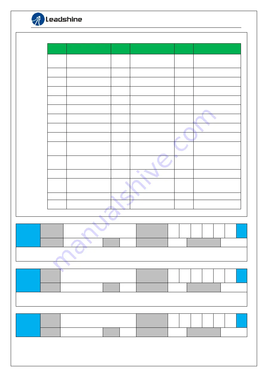
You can select the type of data to be displayed on the front panel LED (7-segment) at the initial status after
power-on.
Setup
value
content
Setup
value
content
Setup
value
content
0
Positional command
deviation
15
Over-load factor
30
Number of abnormal
communication of
encoder
1
Motor speed
16
Inertia ratio
31
Accumulated
operation time
2
Positional command
speed
17
Factor of no-motor
running
32
Automatic motor
identification
3
Velocity control
command
18
No. of changes in
I/O signals
33
Temperature
information
4
Torque command
19
Number of
overcurrent signals
34
Servo state
5
Feedback pulse sum
20
Absolute encoder
data
35
/
6
Command pulse
sum
21
Absolute external
scale position
36
Synchronous period
7
Maximum torque
during motion
22
Absolute multi-turn
position
37
Synchronous loss time
8
23
Communication axis
address
38
Synchronous type
9
Control mode
24
Encoder positional
deviation[encoder
unit]
39
Whether DC is running
or not
10
I/O signal status
25
Motor
electromechanical
angle
40
ACC/DEC
11
/
26
Motor mechanical
Angle
41
Sub-index of OD index
12
Error factor and
reference of history
27
Voltage across PN
42
The value of sub-index
of OD index
13
Alarm code
28
Software version
14
Regenerative load
factor
29
Notes
:
Valid after restart the power.
Pr5.33
Name
Touch probe 1 signal compensation
time
Mode
F
Range
0~32767
Unit
25ns
Default
0
Index
2533h
Time compensation for signal acquisition of touch probe 1 to provide more accurate capture position and
prevent the instantaneous jitter of capture during master and slave cooperation
Pr5.34
Name
Touch probe 2 signal compensation
time
Mode
F
Range
0~32767
Unit
25ns
Default
0
Index
2534h
Time compensation for signal acquisition of touch probe 2 to provide more accurate capture position and
prevent the instantaneous jitter of capture during master and slave cooperation
Pr5.37
Name
Torque saturation alarm detection
time
Mode
F
Range
0~5000
Unit
ms
Default
500
Index
2537h