BL55-RU
(E)
3-5
25
(0.984")
10
(0.394")
10
(0.394")
10
(0.394")
25
(0.984")
A (alignment surface)
20
(0.787")
B (alignment surface)
C (alignment surface)
D (alignment surface)
Alignment position
Alignment position
Alignment position
Foot plate
Unit: mm (inch)
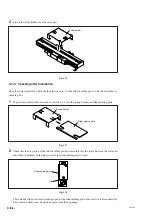
3-4-2. Scale Unit Installation
Parallelism and flatness of the alignment surface
Fig. 3-6
Attach the scale unit so that the parallelism and flatness of the alignment surface are as shown in Table 3-1.
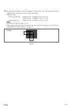
Scales with measuring length of 470 mm or less (without foot plate)
Screw/Tightening torque: ........ M8
×
25: 2 pcs. / 22 N
·
m
Scales with measuring length of 520 mm or more (with foot plate)
Screw/Tightening torque: ........ M8
×
25: 2 pcs. / 22 N
·
m
Screw/Tightening torque: ........ M4
×
25: 1 or 2 pcs. / 2.7 N
·
m
Washer: .................................... Spring washers with nominal size 4: 1 or 2 washers
Measuring length of
Side A flatness
0.1 mm (0.0039") or less
70 or 120 mm
Side B flatness
0.05 mm (0.0019") or less
Parallelism with respect to side A machine runway
0.05 mm (0.0019") or less
Parallelism with respect to side B machine runway
0.05 mm (0.0019") or less
Measuring length of
Side A flatness
0.1 mm (0.0039") or less
170 mm or more
Side B flatness
0.05 mm (0.0019") or less
Parallelism with respect to side A machine runway
0.1 mm (0.0039") or less
Parallelism with respect to side B machine runway
0.1 mm (0.0039") or less
Table 3-1
Attach so that the alignment position for the side A has the range shown in Fig. 3-6. The values for the
allowable range in Table 3-1 assume that there are no sudden shifts on the surface.
Содержание BL55-RU
Страница 2: ...BL55 RU ...
Страница 14: ...1 4 E BL55 RU ...
Страница 30: ...3 14 E BL55 RU ...
Страница 40: ...4 10 E BL55 RU ...
Страница 48: ...7 2 E BL55 RU ...
Страница 50: ...8 2 E BL55 RU ...
Страница 62: ...1 4 G BL55 RU ...
Страница 78: ...3 14 G BL55 RU ...
Страница 88: ...4 10 G BL55 RU ...
Страница 96: ...7 2 G BL55 RU ...
Страница 98: ...8 2 G BL55 RU ...


