


BL55-RU
(E)
4-1
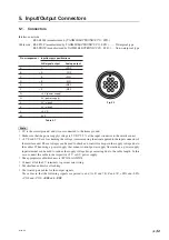
4. Interface Unit
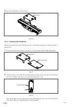
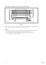
4-1. Installing the Interface Unit
Use the supplied screws to secure and attach the interface unit.
Firmly screw in the output connector.
Screw/Tightening torque ... M4
×
12: 2 pcs. / 2.7 N
·
m
Do not insert or remove the output connector while power is supplied to the interface unit.
Fig. 4-1
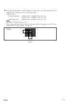
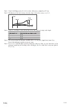
4-2. Removing and Attaching the Interface Unit Cover
To set or check the functions, remove the four screws, and then take off the interface unit cover.
To attach the interface unit cover, tighten the removed screws in their original positions.
Tightening torque ......... 0.3 N
·
m
Be careful not to lose the screws when you remove them.
Fig. 4-2
Содержание BL55-RU
Страница 2: ...BL55 RU ...
Страница 14: ...1 4 E BL55 RU ...
Страница 30: ...3 14 E BL55 RU ...
Страница 40: ...4 10 E BL55 RU ...
Страница 48: ...7 2 E BL55 RU ...
Страница 50: ...8 2 E BL55 RU ...
Страница 62: ...1 4 G BL55 RU ...
Страница 78: ...3 14 G BL55 RU ...
Страница 88: ...4 10 G BL55 RU ...
Страница 96: ...7 2 G BL55 RU ...
Страница 98: ...8 2 G BL55 RU ...


