CHAPTER 4
OPERATION
4-17
DN-107P displays series
4.4.1.2.
Parameters to define the internal bit r2.
To set up the internal bit r2 parameters A2 and S2 are used.
Parameter S2 is used to set up the activation form and delay or hysteresis.
Parameter A2 is used to set up the trigger level. The most significant digit allows setting
up a negative value.
Parameter S2
Left Digit
Control bit
Right Digit
Set/Reset
0
ON if Value > Parameter A2
0
No delay / No hysteresis
1
ON if Value < Parameter A2
1
Delay 1s
2
Always OFF
2
Delay 2s
3
Delay 4s
4
Delay 6s
5
Delay 10s
6
Hysteresis = 2
7
Hysteresis = 4
8
Hysteresis = 8
9
Hysteresis = 12
4.4.2.
Using functions counter or chronometer
4.4.2.1.
Parameter 7. S1: Activation and temporization conditions of output 1.
ONLY FOR DISPLAYS WITH RELAY OUTPUT WORKING IN LOW FREQUENCIES
(see Error! No s'ha trobat l'origen de la referència.
“ Error! No s'ha trobat l'origen de la re
ferència.
” ).
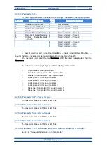
Permits programming the activation conditions of output 1 and the time that will be
activated. This parameter has two digits. The function of each one is explained in the following
table where, value means the value of the counter in the counter function or the time in the timer
function:
Left digit
SR1 output condition
Right digit
Output delay
0
Not activated
0
No delay
1
SR1 ON if Value = Level Alarm 1
1
0,5s delay
2
SR1 ON if Value >= Level Alarm 1
2
0,8s delay
3
SR1 ON if Value = Level Alarm 2
3
1s delay
4
SR1 ON if Value <= Level Alarm 2
4
1,5s delay
5
SR1 ON if Value > Level Alarm 1
5
2s delay
6
SR1 ON if Value < Level Alarm 1
6
0,5s flashing.
7
SR1 ON if Value > Level Alarm 2
7
0,8s flashing
8
SR1 ON if Value < Level Alarm 2
8
1s flashing
9
SR1 ON if Counter = 0
9
Output always OFF
A
SR1 ON if Value <= AL1 and >= AL2
b
SR1 ON if Value >= AL1 and <= AL2
SR1 is the state of the output 1. AL1 is the value of alarm 1. AL2 is the value of alarm 2.
SR1 will be activated when the activation conditions have been accomplished. SR1 will be
deactivated when the time has passed or when the activation condition is not accomplished.
Содержание DN-107P
Страница 1: ...1227K13D OPERATION MANUAL FOR DISPLAY DN 107P ...
Страница 2: ......
Страница 6: ......
Страница 10: ......
Страница 32: ......


