background image

CHAPTER 4 

OPERATION 

4-3 


 DN-107P displays series 


4.2.4.1.


Parameter 2 Co 

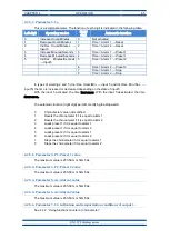
This is a 2-digit parameter. The function of each digit is indicated in the following table. 

Left digit 

Operating modes 

Right 

digit 

Automatic function 

High counting frequency 

Not activated 

Low counting frequency 

Counter = Alarm 1 

→ Reset 


Counter = Alarm 2 

→ Reset 


Counter = Alarm 1 

→ Preset 1 


Counter = Alarm 2 

→ Preset 1 


Counter = Alarm 1 

→ Preset 2 


Counter = Alarm 2 

→ Preset 2 

 
The digit on the left allows to adjust the type of  sensor used. For contact type sensors 

such  as  pushbuttons  or  relays,  the  low  count  frequency  must  be  used  to  eliminate  contact 
bounces. For transistor output sensors such as inductive, photocells, etc. either of them can be 
used considering that the low frequency admits a maximum frequency of 100Hz. 

The automatic function (right digit) allows to modify the value of the counter when it has 

a determinate value. 


Counter’s value not modified. 


Resets the counter if it is equal to alarm 1 


Resets the counter if it is equal to alarm 2 


Loads preset 1 if it is equal to alarm 1 


Loads preset 1 if it is equal to alarm 2 


Loads preset 2 if it is equal to alarm 1 


Loads preset 2 if it is equal to alarm 2 

The automatic function doesn’t work in high frequencies. 
 

4.2.4.2.


Parameter 3. P1: Preset 1 value


It can be from 0 to as many 9 as digits the display has. 

4.2.4.3.


Parameter 4. P2: Preset 2 value 

It can be from 0 to as many 9 as digits the display has. 

4.2.4.4.


Parameter 5. A1: Alarm 1 value 

It can be from 0 to as many 9 as digits the display has. 

4.2.4.5.


Parameter 6. A2: Alarm 2 value 

It can be from 0 to as many 9 as digits the display has. 

4.2.4.6.


Parameter 7. S1: Activation and temporization conditions of output 1. 

See 4.4.2  

“Using functions counter or chronometer” 


4.2.4.7.


Parameter 8. S2: Activation and temporization conditions of output 2 

See 4.4.2  

“Using functions counter or chronometer” 


Содержание DN-107P

Страница 1: ...1227K13D OPERATION MANUAL FOR DISPLAY DN 107P ...

Страница 2: ......

Страница 3: ...4 2 4 Parameters of the function 03 Counter 2 4 2 5 Parameters of function 04 Chronometer 4 4 2 6 Parameters of functions 05 15 and 25 Tachymeter 6 4 2 7 Parameters of function 06 Binary 7 4 2 8 Parameters of function 07 Digit by digit 7 4 3 Functions 8 4 3 1 Function 1 8 bits multiplexed BCD 8 4 3 2 Function 11 8 bits multiplexed BCD 9 4 3 3 Function 2 Direct BCD 10 4 3 4 Function 12 Direct BCD 1...

Страница 4: ...4 4 1 Using functions BCD tachometer binary or digit by digit 16 4 4 2 Using functions counter or chronometer 17 4 4 3 Parameters to define the colour 18 4 4 4 Work with only one colour 19 ...

Страница 5: ...se and decrease Input with fast and low speed selectable Back up for display value if no power supply Tachometer For displays of 3 or 4 digits The display value is proportional to the input frequency Totally configurable Chronometer For displays of 3 or 4 digits It lets you configure a chronometer with hours minutes or minutes seconds running in increment or decrement The display has inputs for pr...

Страница 6: ......

Страница 7: ...63Hz Optional 24V Consumption 35VA Display 7 segments 57mm high decimal point Red led colour Viewing distance max 30 meters Parameter memory Eeprom Control inputs 12 to 24VCC PNP NPN or Contact Relay option R Contact SPDT Maximum 48V 1A Environmental Conditions Operation Temperature 20 to 60ºC Storage Temperature 30ºC to 70ºC Humidity 5 95 RH non condensing Maximum environmental illumination 1000 ...

Страница 8: ... series DN 107P 2 2 Dimensions and fixing of the displays 2 2 1 Dimensions of the displays DN 107 3 245 120 70 40 All the measurements are in millimeters 2 2 2 Dimensions of the displays DN 107 4 245 120 70 40 All the measurements are in millimeters ...

Страница 9: ...CAPÍTULO 2 CARACTERÍSTICAS GENERALES 2 3 DN 107P displays series 2 2 3 Fixing of the displays 100 150 400 600 90 º 73 5 7 15 52 52 All the measurements are in millimeters Fixing plate M8 ...

Страница 10: ......

Страница 11: ...ed in places with an illumination level in excess of 1000 lux Neither should the display be placed in direct sunlight as visibility would be lost In the electrical installation proximity to lines of high intensity circulation and high voltage lines must be avoided as well as proximity to High Frequency generators and U F converters for motors 3 1 Power supply The power supply must be 88 to 264 VAC...

Страница 12: ...E11 E10 E14 Vcc 0V COM SR1 SR2 PNP NPN DB25 MALE CONECTOR Auxiliary output voltage DN 109 12V DN 119 12V DN 119C 24V DN 129 24V DN 189 24V Do not connect a power supply Each input has a different use depending on the function BCD counter etc To know how to wire them see 4 3 Functions The inputs power supply must be between 12V and 26V CC with a maximum wave of 500mV Surpassing these values can dam...

Страница 13: ...by the digit on the left and the decimal point flashes while the digit on the right is off 4 2 1 Enter to modify parameters In order to enter the sequence to modify the parameters the Advance key must be pressed and held for three seconds After this the first parameters will be displayed with the digit flashing There are then two options 1 Modify the parameter value By pressing the Advance key the...

Страница 14: ...See what each function does in 4 3 Functions In 01 11 8 bit multiplexed BCD and 02 12 direct BCD functions the function is the only parameter configurable The chronometer function 14 is used in displays with format HH MM This function lets to display the parameter number on the fourth digit 4 2 4 Parameters of the function 03 Counter Parameter 2 Co Multiplying or splitter factor maximum frequency ...

Страница 15: ...dify the value of the counter when it has a determinate value 0 Counter s value not modified 1 Resets the counter if it is equal to alarm 1 2 Resets the counter if it is equal to alarm 2 3 Loads preset 1 if it is equal to alarm 1 4 Loads preset 1 if it is equal to alarm 2 5 Loads preset 2 if it is equal to alarm 1 6 Loads preset 2 if it is equal to alarm 2 The automatic function doesn t work in hi...

Страница 16: ... 2 4 10 Parameter B So Exit modify parameters In order to exit the sequence for modifying parameters select the last parameter in the menu Then press See the input wiring and examples in 4 3 Functions 4 2 5 Parameters of function 04 Chronometer The chronometer format and its maximum value depends on the display s digit number 3 Digits display D DD Maximum value 9 59 4 Digits display DD DD Maximum ...

Страница 17: ...me increases With the input 5 deactivated the time decreases The automatic function right digit permits modifying the stopwatch 0 Chronometer value not modified 1 Resets the chronometer if it is equal to alarm 1 2 Resets the chronometer if it is equal to alarm 2 3 Loads preset 1 if it is equal to alarm 1 4 Loads preset 1 if it is equal to alarm 2 5 Loads preset 2 if it is equal to alarm 1 6 Loads ...

Страница 18: ... digits Maximum frequency Minimum frequency 3 999 0 01 4 9999 0 001 The decimal point is selected with the increase key after programming the frequency 4 2 6 2 Parameter 3 dI Value of the display Selects the number shown when the frequency is equal to the input frequency of parameter 2 Number of digits Maximum value Minimum value 3 999 0 01 4 9999 0 001 The decimal point is selected with the incre...

Страница 19: ... you don t want to see it the average factor reduces the change Each time that the data is updated the new number erase the oldest The possible values are from 0 to 9 The number of samples are the average factor multiplied 5 4 2 6 7 Parameter B So Exit modify parameters In order to exit the sequence for modifying parameters select the last parameter in the menu Then press See the input wiring and ...

Страница 20: ...and E6 If the four inputs are 0 with the E1to E4 the decimal point position is codified If not they codify the digit s position and E1 E2 E3 and E4 are the code of the value The digit 1 is in the right of the display Decimal point position Digit No point 1 2 3 4 E1 0 1 0 1 0 E2 0 0 1 1 0 E3 0 0 0 0 1 E4 0 0 0 0 0 Point selection Digit point selection 1 2 3 4 ºE5 0 1 0 1 0 E6 0 0 1 1 0 Function Sym...

Страница 21: ...ue 1 2 7 4 Example 2 Modifying the decimal point position Initial display value 1 2 3 4 Display the decimal point in the value 3 E8 E6 E5 E4 E3 E2 E1 0 0 0 0 1 0 0 E1 E4 Decimal point position E5 E7 Modify the decimal point position This data must be stable for 5ms E8 High Strobe E8 E6 E5 E4 E3 E2 E1 1 0 0 0 1 0 0 This data must be stable for 5ms Final display value 1 2 3 4 4 3 2 Function 11 8 bit...

Страница 22: ...al point of the digit 2 Central digit The input E14 controls the decimal point of the digit 3 Left digit The function of each input is explained in the following table 3 2 1 E14 E13 E12 E11 E10 E9 E8 E7 E6 E5 E4 E3 E2 E1 The values shown depending on the inputs are Displayed value Function 02 0 1 2 3 4 5 6 7 8 9 A b C d E F Function 12 0 1 2 3 4 5 6 7 8 9 A b C d E Space E1 E5 E9 0 1 0 1 0 1 0 1 0...

Страница 23: ... value of 999 Programming the automatic functions The automatic functions are programmed modifying the right s digit of the second parameter 2 Co See 4 2 4 Parameters of the function 03 Counter Remember that the automatic functions are available in low frequencies When the counter s value is equal to one of the values of the alarms one programmed action starts Example Parameter 2 Co 03 Parameter 3...

Страница 24: ... programmed action starts Example Parameter 2 Co 35 Parameter 4 P2 15 30 Parameter 5 A1 30 28 The parameter 2 has programmed increase minutes and seconds Load the preset 2 15m 30s when the chronometer is equal to the alarm 1 value 30m 28s Displays with relay If the display has the relay option the relay can be configured to be activated in different situations Each relay has an independent paramet...

Страница 25: ...amples below Connexion the input signal of the function tachometer is E6 the pin number 6 of the DB25 connector see 3 2 Wiring inputs The maximum input frequency is 15kHz Before using the tachometer you have to program the parameters See 0 In order to exit the sequence for modifying parameters select the last parameter in the menu Then press See the input wiring and examples in 4 3 6 Function 4 Ch...

Страница 26: ...imum time without pulses 1s 6 Pd 0 Without decimals 7 FA 0 Without average factor Measure the making cadence of a machine that makes 450 pieces in an hour with a sensor that detects a piece each 8 seconds A little stable oscillator 4 digits display Parameter Value 2 FE 0 125 0 125 input frequency 1 piece each 8s 3 dl 0450 Display 450 when 0 125 Hz input frequency 4 EL 020 Update value every 2 5 LI...

Страница 27: ...Binary The function 6 permit display a 9 bits binary value in decimal format Value 0 is shown with all inputs OFF and value 512 is shown with all inputs ON The parameter A Pu allows configuring the decimal point position 4 3 11 Parameter 7 Digit by digit Function 7 allows the user to modify every digit independently using an input If the display has more than 7 digits each of the inputs increments...

Страница 28: ...hange must be related with the relay activation The following table defines the parameters depending on the function used in the display BCD Count Chronom Tachym Binary Digit by digit A1 8 A1 5 A1 5 A1 8 A1 8 A1 8 A1 A2 9 A2 6 A2 6 A2 9 A2 9 A2 9 A2 S1 A S1 7 S1 7 S1 A S1 A S1 A S1 S2 B S2 8 S2 8 S2 B S2 B S2 B S2 nr r1 y r2 deactivated r1 r1 activated r2 r2 activated r3 r1 y r2 activated 4 4 1 Us...

Страница 29: ...mits programming the activation conditions of output 1 and the time that will be activated This parameter has two digits The function of each one is explained in the following table where value means the value of the counter in the counter function or the time in the timer function Left digit SR1 output condition Right digit Output delay 0 Not activated 0 No delay 1 SR1 ON if Value Level Alarm 1 1...

Страница 30: ...vel Alarm 2 7 0 8s flashing 8 SR1 ON if Value Level Alarm 2 8 1s flashing 9 SR1 ON if Value 0 9 Output always OFF A SR1 ON if Value AL1 and AL2 b SR1 ON if Value AL1 and AL2 SR2 is the state of the output 2 AL1 is the value of alarm 1 AL2 is the value of alarm 2 SR2 will be activated when the activation conditions have been accomplished SR1 will be deactivated when the time has passed or when the ...

Страница 31: ... Counter Tachometer Chronometer Binary Digit by digit Parameter Value 8 A1 5 A1 0 9 A2 6 A2 0 A S1 7 S1 20 B S2 8 S2 20 nr nr colour r1 r1 colour r2 r2 colour r3 r3 colour Parameters 8 A1 9 A2 5 A1 and 6 A2 may have any value Parameters nr r1 r2 and r3 should have the same colour Independently of work colour the parameters set up always uses RED colour ...

Страница 32: ......

Страница 33: ...he aforementioned product complies with the following European directives Directive LVD 2006 95 CEE Low Voltage Directive Standard UNE EN61010 1 Security in electric equipment Directive EMC 2014 30 UE Electromagnetic Compatibility Standard UNE EN 61000 6 4 Generic Emission Standard Industrial environment Directive 2011 65 CE Restriction of the use of certain hazardous substances in electrical and ...

Отзывы: