4-4 FIELD OPERATION
4-4.1
After transporting the machine to the field,
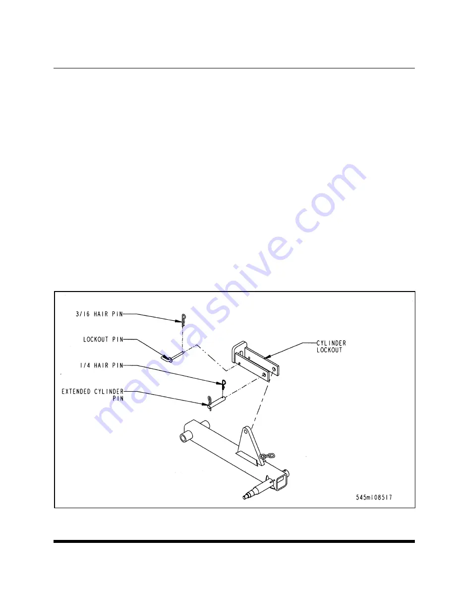
disengage the cylinder lockouts and secure
the lockouts to the chain on the gauge wheel
arm
(See Figure 4-1).
4-4.2
On fold models only, with tractor running at
fast idle, unfold wings.
4-4.3
Lower the machine until the points are run-
ning at the desired depth. Then adjust the ra-
dius rod so the plow frame is parallel with
the ground and all points are cutting the
same depth.
4-4.4
Set the depth by adjusting the stroke con-
trol on the master cylinders. For stability, it is
important the the gauge wheels always apply
slight pressure against the soil.
4-4.5
Operate machine a few yards and recheck
depth and level operation.
4-4.6
Select proper speed (from 5 to 7 miles per
hour) for best plowing results.
4-4.7
Speed should be reduced at the ends of
the field and turning may require use of the
tractor steering brakes. Do not make high
speed turns at any time.
4-4.8
Always raise the machine completely out
of the ground when turning or backing up, to
prevent shank breakage and coulter gang
damage, and to rephase the lift cylinders.
4-4.9
It is important to keep all bolts tight at all
times, especially during the first few hours of
operation. After break-in period, check them
periodically. Loose bolts can result in lost,
broken, or prematurely worn parts and un-
necessary down time.
4-4.10
Coulter gang depth should be adjusted so
that they operate only deep enough to be in
firm soil and cut the residue. Generally, the
harder the soil, the less pressure should be
used on the coulter gangs.
NOTE: It is customary for scrapers on the coul-
ter gangs to wear a groove into the spools.
This helps to keep scrapers in alignment and to
allow them to work more effectively.
4-3
Figure 4-1 Cylinder Lockouts
Содержание SOIL MASTER II 1200 Series
Страница 3: ...MODEL 1200 SERIES SOIL MASTER II OPERATOR S MANUAL PURCHASED FROM DATE ADDRESS PHONE NO SERIAL NO...
Страница 7: ......
Страница 11: ...2 4 Figure 2 1 Rigid 7 9 Shank Spacing...
Страница 12: ...2 5 Figure 2 2 Rigid 11 Shank Spacing...
Страница 13: ...2 6 Figure 2 3 Rigid 13 Shank Spacing...
Страница 14: ...2 7 Figure 2 4 Wing 15 Shank Spacing...
Страница 15: ...2 8 Figure 2 5 Wing 17 Shank Spacing...
Страница 16: ...2 9 Figure 2 6 Wing 19 Shank Spacing...
Страница 17: ...NOTES 2 10...
Страница 19: ...3 2 Figure 3 1 Frame Assembly Rigid...
Страница 21: ...3 4 Figure 3 2 Frame Assembly Folding...
Страница 29: ...3 12 Figure 3 7 Hydraulic Fold Assembly...
Страница 31: ...3 14 Figure 3 8 Pull Hitch Installation...
Страница 33: ...3 16 Figure 3 9 Coulter Gang Installation...
Страница 34: ...3 17 Figure 3 10 Coulter Depth Adjustment...
Страница 35: ...3 18 Figure 3 11 Coulter Gang Hydraulic Assembly...
Страница 37: ...3 20 Figure 3 12 Clamp Assemblies...
Страница 39: ...3 22 Figure 3 13 Electrical Installation...
Страница 41: ...3 24 Figure 3 14 1200 Series Decal Placement 1 of 2...
Страница 42: ...3 25 Figure 3 15 1200 Series Decal Placement 2 of 2...
Страница 51: ......
Страница 53: ...NOTES 5 3...
Страница 54: ......


