


4-7 SUSPENSION MAINTENANCE
4-7.1
Air Ride Suspension
a.
Physically check all nuts, bolts, and air line
fittings for proper torque (see torque chart be-
low).
AIR SUSPENSION TORQUE CHART
Size
1-1/8"-7
1/2"-13
*3/4"-16
3/4"-10
Torque in
Ft. Lbs.
800
35
35
150
* Air Spring Connections Only.
b.
Check all other suspension components for
any sign of damage, looseness, wear or
cracks.
c.
With trailer on level surface and air pressure
in excess of 65 psi, all air springs should be of
equal firmness.
The height control valve on
right side of rear axle controls all air
springs.
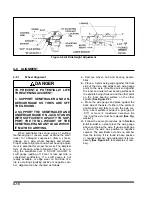
4-7.2
Air Ride Height Adjustment (See Fig-
ure 4-6
for parts identification)
.
a.
Before adjusting, the vehicle must be empty
with the kingpin at operating height and have
air supplied to the semitrailer.
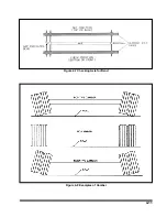
b.
Disconnect linkage at the control arms and
raise control arms to the “up” position, raising
the semitrailer the full extent of suspension
travel.
c.
Position the wood block between the axle
tube and frame according to table below.
AIR SUSPENSION
RIDE HEIGHT AND BLOCK
Brake Size
Ride Height
Block Height
12-1/4" Dia.
3.5"
4-1/4"
d.
Lower the semitrailer by exhausting all air
from the system. Recheck the ride height.
e.
Move the control arms to the “down” posi-
tion (about 45°) for 10-15 seconds. Slowly re-
turn the control arms to the center position
and insert locating pins into the adjusting
block and bracket on the automatic height
control valves
(See Figure 4-6)
.
f.
Loosen the 1/4" adjusting lock nut located
on the adjusting blocks, allowing the control
arm to move approximately 1 inch.
g.
Reconnect the linkage to the control arm
lower brackets and re-tighten the 1/4" adjust-
ing lock nut to 2-4 ft.lbs.
h.
Remove the locator pins, pressurize the
semitrailer air system, and raise the semi-
trailer. The height control valves may be used
as an improvised jack by disconnecting the
control arms at the lower bracket and pushing
the control arms to an “up” position.
i.
Remove the spacers, exhaust the system
and reconnect the linkage. This allows the
Automatic Height Control Valves to resume
normal operation.
j.
Check the air ride height. If necessary, go
through the adjustment procedure again until
the proper air ride height is achieved.
k.
Check the air ride height periodically and
adjust as needed.
4-9
Содержание 336C
Страница 3: ...MODEL 336C CAR CARRIER OPERATOR S MANUAL PURCHASED FROM DATE ADDRESS PHONE NO SERIAL NO...
Страница 8: ......
Страница 24: ...3 12 Figure 3 7 Lining Up the Over the Cab Deck Figure 3 8 Loading the Over the Cab Deck...
Страница 28: ...3 16 Figure 3 11 Loading the Lower Deck...
Страница 32: ...3 20 Figure 3 13 Rear Impact Guard and Antilock Brake System...
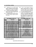
Страница 40: ...4 6 Figure 4 3 336C Wiring Diagram...
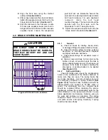
Страница 45: ...4 11 Figure 4 7 Checking Axle for Bend Figure 4 8 Examples of Camber...
Страница 50: ...4 16 Figure 4 12 Axle and Brake Assembly...
Страница 54: ...4 20 Figure 4 14 Outboard Mount Hub and Drum Figure 4 15 Inboard Mount Hub and Drum...
Страница 59: ...4 25 Figure 4 19 Mounting Tires and Wheels Figure 4 20 Stud Tightening Sequence...
Страница 70: ...NOTES 5 10...


