


3-22 ANTI-LOCK BRAKE SYSTEM (ABS)
Vehicle standards FMVSS No. 121 anti-lock
brake system requires all trailers with air brake
systems to have ABS after March 1, 1998. Each
trailer (including a trailer converter dolly) shall be
equipped with an anti-lock brake system that con-
trols the wheels of at least one axle of the trailer.
Wheels on other axles of the trailer may be indi-
rectly controlled by the anti-lock brake system.
NHTSA Docket 92-29; notice 11 published
September 23, 1996 specifies the ABS warning
light be mounted near the rear of the left side of
the trailer
(See Figure 3-13).
·
Decal or lens marking with ABS to identify
the lamp
·
The lamp must illuminate one time whenever
power is supplied to the ABS. When the
light remains on while power is supplied
and the vehicle has been pulled faster than
4 mph, there is a malfunction of the system.
The ABS used on the semitrailer is a commer-
cial unit. Single axle trailers use a two wheel sen-
sor and one valve system. The valve is an ABS re-
lay valve with integrated electronic control unit. The
wheel sensors check for wheel lock-up. The valve
modulates both sides of trailer if either side starts
to lock up.
Tandem axle and triple axle trailers use a four
wheel sensor and two valve system. Sensors are
located on the front and rear axles. Even triple axle
trailers with lift axle have wheel sensors on the
front and rear axles because the ECU can detect
when the axle is lifted and will disregard it’s read-
ing. One of the valves is an ABS relay valve with
integrated electronic control unit. The other valve is
an ABS relay valve that is controlled by the elec-
tronic control unit on the first valve. The valve with
the integrated electronic control unit controls the
brakes on the right side of the trailer. The other
valve controls the brakes on the left side of the
trailer. For example, if either the front or the rear
axle on the right side of the trailer begin to lock up,
the valve with the integrated electronic control unit
will modulate all the brakes on the right side of the
trailer to prevent the lock-up.
It is important that all the wheel sensor wires
go to the correct connection on the integrated elec-
tronic control unit so the valves modulate the cor-
rect brakes and so the diagnostic codes are cor-
rect.
The ABS is constant powered by the auxiliary
(blue) circuit, center pin on the semitrailer seven
way electrical connector. This circuit must be hot
whenever the tractor key switch is on. This circuit
must also not be used to power any additional de-
vices while the semitrailer is moving forward. How-
ever, additional devices such as remote controls
may be powered from the the auxiliary circuit while
the semitrailer is stationary. Back up power to the
ABS is supplied through the stop lamp (red) circuit,
No. 4 pin on the seven way connector, and ground
is supplied by the white wire, No. 1 pin.
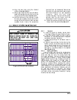
CAUTION
THE AUXILIARY (BLUE) CIRCUIT IS
FOR POWERING THE SEMITRAILER
ABS. THIS CIRCUIT MUST BE HOT
WHEN THE TRACTOR KEY SWITCH IS
ON. NO OTHER ELECTRICAL DEVICES
MAY BE POWERED BY THIS CIRCUIT
WHILE THE SEMITRAILER IS MOVING
FORWARD.
3-21
Содержание 336C
Страница 3: ...MODEL 336C CAR CARRIER OPERATOR S MANUAL PURCHASED FROM DATE ADDRESS PHONE NO SERIAL NO...
Страница 8: ......
Страница 24: ...3 12 Figure 3 7 Lining Up the Over the Cab Deck Figure 3 8 Loading the Over the Cab Deck...
Страница 28: ...3 16 Figure 3 11 Loading the Lower Deck...
Страница 32: ...3 20 Figure 3 13 Rear Impact Guard and Antilock Brake System...
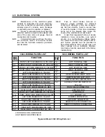
Страница 40: ...4 6 Figure 4 3 336C Wiring Diagram...
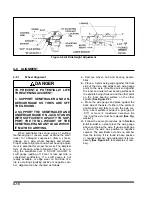
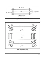
Страница 45: ...4 11 Figure 4 7 Checking Axle for Bend Figure 4 8 Examples of Camber...
Страница 50: ...4 16 Figure 4 12 Axle and Brake Assembly...
Страница 54: ...4 20 Figure 4 14 Outboard Mount Hub and Drum Figure 4 15 Inboard Mount Hub and Drum...
Страница 59: ...4 25 Figure 4 19 Mounting Tires and Wheels Figure 4 20 Stud Tightening Sequence...
Страница 70: ...NOTES 5 10...


