


15
FEATURES OF THE TWIN POUR 30 DISPENSER
Time & Delay Features
1. From the Service Menu, tap the
Time & Delays
button to
access the Time & Delays Menu.
2. Enable or Disable any of the three (3) time & delay functions
by tapping underneath their designated function names:
Brand Timeout, Screen Saver,
and
Sleep
.
3. Adjust the
Frequency
and
Units of Time
by tapping the “+“
and “-“ buttons.
Brand Timeout - the amount of time for a selected
brand on the Pour Screen to be deselected after
inactivity
Screen Saver - the amount of time for the screen saver
to be initiated after inactivity
Sleep - the amount of time for the unit to enter Sleep
Mode after inactivity.
Dispense Timeout - the amount of time a valve will pour
before automatic shutoff.
NOTE
Ready - signifies there is available product and the
valve will dispense when activated
Out - signifies there is no available product or there is
a problem with the specified brand and will dispense
when activated.
Auto - signifies that the configured Sold Out Sensor
controls whether the brand can be dispensed. This
feature requires an optional sold out sensor kit, does
not come standard, and is available for up to ten
(16) brands at one time. The following is a set of
instructions on how to set up this feature. If no sold out
sensor is assigned then the Auto feature acts the same
as the Ready feature.
NOTE
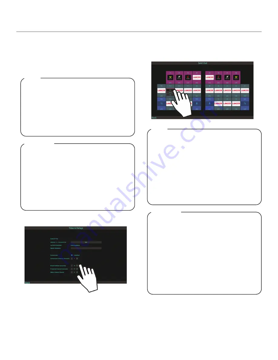
Sold Out Features
1. From the Service Menu, tap the
Sold Out
button.
2.
Manually adjust specific brands to read
Ready, Out,
or
Auto
Brand Timeout - la durée pendant laquelle une marque
sélectionnée sur l’écran de versement doit être
désélectionnée après inactivité
Économiseur d’écran - la durée pendant laquelle
l’économiseur d’écran doit être lancé après l’inactivité
Veille - la durée pendant laquelle l’unité passe en mode
veille après une inactivité.
Dispense Timeout - la durée pendant laquelle une
vanne coulera avant l’arrêt automatique.
REMARQUE
Prêt - signifie qu’il y a un produit disponible et que la
vanne distribuera lorsqu’elle est activée
Out - signifie qu’il n’y a pas de produit disponible ou
qu’il y a un problème avec la marque spécifiée et sera
distribué lorsqu’il est activé.
Auto - signifie que le capteur épuisé configuré contrôle
si la marque peut être distribuée. Ce la fonction néces-
site un kit de capteur en option épuisé, n’est pas livré
en standard et est disponible pour un maximum de
dix (16) marques à la fois. Ce qui suit est un ensemble
d’instructions sur la façon de configurer cette fonction.
Si aucun capteur épuisé n’est attribué, la fonction Auto
agit de la même manière que la fonction Prêt.
REMARQUE
Содержание Twin Pour 30
Страница 29: ...29...
Страница 30: ...A HOSHIZAKI COMPANY 6655 Lancer Boulevard San Antonio TX 78219 lancerworldwide com...


