background image


26


CONNECTOR PIN-OUTS;   INTERCONNECT   INFORMATION 

 
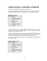
Connector pinouts for the frame connectors are listed below.  
 
Connections to the devices are standard RS-422 links.  The data format is SMPTE 
standard 38.4K baud, Odd parity.   The control protocol is standard Sony/Odetics. 


Device A,B, C, D Ports    


Pin # 

Function 

Ground 

-RX Data (from device) 

+TX Data (to device) 

Ground 

(no connection) 

Ground 

+RX Data (from device) 

-TX Data (to device) 

Ground 


P-bus  connections  are  also  standard  SMPTE  device  end  pinouts.    The  two 
connectors are identical and connected together.   The P-bus port on the TDC-100B 
is listen only, as of firmware version 1.1. 
 
The data is RS-422, 38.4K baud, and the parity is selectable in the TDC-100B menu.  
Parity is normally selected to be Odd.  Parity selected must match the switcher, or a 
‘Parity Error’ message will result, and the P-bus command will be ignored. 
 
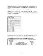
The  P-bus  protocol  is  the  Grass  Valley  P-bus  control  standard,  also  supported  by 
Sony, Ross, and others. 


P-Bus In and P-Bus Loop


Pin # 

Function 

Ground 

Loop to other connector 

+RX Data(from switcher) 

Ground 

(no connection) 

Ground 

Loop to other connector 

-RX Data (from switcher) 

Ground 


Содержание TDC-100B

Страница 1: ...ut 06877 TDC 100B TD S DISK CONTROLLER Preliminary Installation and Operation Manual Software Version 1 1 Lance Design 27 Fairview Avenue Ridgefield Connecticut 06877 Tel 203 894 8206 www lancedesign...

Страница 2: ...will be made free of charge provided that the equipment has not been subjected to mechanical or electrical abuse or modification as determined by Lance Design and also that the equipment is returned t...

Страница 3: ...Description Page 7 Menu Items Page 9 General Operation Page 14 Trigger Function Numbers Page 15 Multi Device Control Rules Page 17 Multi Point Loops Page 18 USB Port Operation Page 19 Installation Pag...

Страница 4: ...G button the MARK IN button and the MARK OUT button at the same time 3 buttons at once The display will say CLR To Clear All If you press the CLR key while holding down the above three buttons the TDC...

Страница 5: ...in time adds a duration value to it and stores it in the out register To display the duration of a register difference between in point and out point press TM key If either of the registers is clear t...

Страница 6: ...will stop looping at the first opportunity and play to the outside outpoint register 25 outpoint in the above example To Do an Automatic Transfer Dub from a vtr Set inpoints for both the vtr playback...

Страница 7: ...l Numeric Keypad for entry of numeric data register numbers timecodes etc Plus and Minus Keys for timecode arithmetic and for use as up down keys for scrolling through the menu items FCN Key for selec...

Страница 8: ...ll toggle the menu choices if there are only two If there are more than two it will step through them If you hold this key down you can use the knob to adjust the menu setting CLIP LIST used to displa...

Страница 9: ...ll the register and immediately cue the disks to the register inpoints P bus recalls will always cue the disks regardless of this menu setting This would normally be set to Only when loading the times...

Страница 10: ...07 RECALL DISPLAYS NAME TIME This item applies only if Item 04 is turned on If this item is set to NAME the clip name will be displayed when a register is recalled If this item is set to TIME the In T...

Страница 11: ...ing multiple machines if the device number s from the switcher match any of the enabled machines the commands will be sent to all enabled machines Setting this item to assigns no device number to chan...

Страница 12: ...Channel C exits a Multi loop GPI Out 3 Triggered when Channel D exits a Multi loop GPI Out 4 Triggered when any of the four channels exits a Multi loop 28 GPI OUTPUTS ACTIVE LOW HIGH Selects the polar...

Страница 13: ...tify them as Sony VTR If they are in Non BVW modes the TDC will try to report what protocol is selected The frame rate of the controlled device will also be displayed TDC FIRMWARE VERSION Displays the...

Страница 14: ...ecalls and learns SWITCHER INITIATED FUNCTIONS The production switcher can do the following things 1 Issue LEARN commands This happens when you do a emem learn with learn recall enabled in the emem pe...

Страница 15: ...send a trigger When the switcher sends a TRIGGER all enabled machines are sent a command corresponding to the Function Number specified for that trigger in the switcher menu The function numbers are a...

Страница 16: ...valid inpoints and valid device numbers will be cued All 300 registers are directly accessible from P bus if the switcher supports this expanded access This may make the use of SELECT BANK triggers un...

Страница 17: ...you do put this trigger in your effect you may be causing two cueup commands to be sent to the DDR at almost the same time and this might actually slow the cueing process or cause other DDR problems T...

Страница 18: ...loop must have a minimum duration of 1 15 just like a normal loop and must have both an inpoint and an outpoint The Start Point must be at least as early as the Loop In point There are no requirement...

Страница 19: ...by both the Windows and the Mac versions of the Cueman applications Files may be freely interchanged between the USB flash drives and the Cueman applications The menu data is stored in files with a td...

Страница 20: ...by pressing the MENU SET button just below the MENU button You may return to the main menu at any time except when a file read write is in progress by pressing the MENU button The eight main menu fun...

Страница 21: ...d warning is displayed if the versions differ This is because menu items may have changed between different versions and the file may not give you the settings you expect The menu items for the origin...

Страница 22: ...ector for extending P bus connections to other devices CONTROL PANEL Ethernet RJ45 with POE RS 232 GPI RS 232 port for PC upload download of register data and GPI input and output connections EXT REF...

Страница 23: ...DEO CONNECTIONS The BNC connectors on the rear panel are for analog reference video Note that this input must be composite analog black or other analog video synchronous with the video system with whi...

Страница 24: ...ction or by a standard POE switch or POE power inserter The power requirements are modest The panel draws approximately 3 to 4 watts of POE power Note that it often takes a few seconds for the control...

Страница 25: ...the Ethernet connector and the first three sections of the switch on the rear of the frame must match for the panel and frame to communicate Multiple TDC 100Bs may communicate over the same network s...

Страница 26: ...device end pinouts The two connectors are identical and connected together The P bus port on the TDC 100B is listen only as of firmware version 1 1 The data is RS 422 38 4K baud and the parity is sel...

Страница 27: ...1 stop bit 9600 8 N 1 GPI RS 232 Pin Function 1 Ground 2 RS 232 RX to TDC100 3 RS 232 TX from TDC100 4 GPI In 2 5 GPI In 4 6 GPI Out 1 7 GPI Out 3 8 GPI Out 5 9 Ground 10 Ground 11 GPI In 1 12 GPI In...

Страница 28: ...28 Notes...
Отзывы: