24
CONTROL PANEL CONNECTIONS
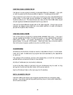
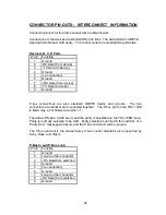
The frame to control panel connection is standard Ethernet (100baseT). The ports
on both the panel and the frame are MDI-X capable. The data protocol is UDP.
The connection may be direct, from the panel to the frame using a standard Ethernet
(Cat5) cable, or may pass through standard IT infrastructure, such as switches,
media converters, etc. The data packets are small, and the TDC-100B traffic should
not add significant additional bandwidth load to any network.
The normal copper Ethernet length limit of 100 meters applies. If very long runs are
required, we suggest using a fiber link, and suitable switches or media converters to
provide the copper-to-fiber interface.
CONTROL PANEL POWER
The control panel is powered by standard POE (IEEE802.3af) power. This power
may be supplied by the frame, if a direct connection, or by a standard POE switch or
POE power inserter. The power requirements are modest. The panel draws
approximately 3 to 4 watts of POE power. Note that it often takes a few seconds for
the control panel to power up after connection to a POE source.
IP ADDRESSING
IP addresses for the frame and panel must be compatible for them to communicate.
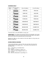
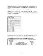
There are 8 pairs of addresses pre-programmed and selectable by the dipswitches
on each unit.
The settings of the first three sections of the dipswitches on both the control panel
and the frame must match for them to communicate.
All of the IP addresses are local subnet addresses.
As far as the TDC-100B is concerned, any pair of addresses may be used, so long
as they don’t conflict with another device on the same network.
See the IP Address Table on the next page for IP selections.
NOTE – MAGNETIC FIELDS
The TDC-100B control panel uses magnetic reed switches and a magnetic rotary
encoder. Very strong external magnetic fields may cause control panel malfunction
and should be avoided.
Содержание TDC-100B
Страница 28: ...28 Notes...

