22
INSTALLATION AND CONNECTIONS
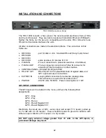
TDC-100B Frame, Rear Panel
The TDC-100B consists of two pieces: the rack-mounted electronics frame (1RU)
and the control panel. They are interconnected with standard Ethernet (100baseT).
Neither the frame nor the panel is compatible with the older TDC-100s which use
RS-422 communication between the units.
All other connections are made to the electronics frame. The connectors on this
frame are:
DEVICE A
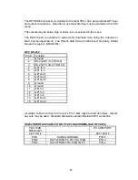
- port for disk or vtr A. Standard RS-422 (Sony 9-pin) format
DEVICE B
DEVICE C
DEVICE D
- same as above for devices B, C, D.
P-BUS IN
- P-bus II connection to production switcher - 38.4K Baud
P-BUS LOOP
- Pin-to-pin looping connection to P-Bus IN connector for
extending P-bus connections to other devices.
CONTROL PANEL – Ethernet (RJ45) with POE.
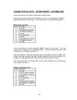
RS-232 / GPI
- RS-232 port for PC upload/download of register data, and
GPI input and output connections.
EXT REF IN
- Looping BNC connectors for reference (analog) video.
This reference is required for accurate control.
POWER
- 95-250 volts, 50/60 Hz. Power consumption is <10W
GPI INPUT CONNECTIONS
The GPI inputs can be enabled in the menu, and have the following fixed
assignments:
GPI 1 - Stop
GPI 2 - Play
GPI 3 - Recue
GPI 4 - Recall Register 000
GPI 5 - Recall Register 001
Electrically, the inputs are a 74HC - series input (will accept ‘TTL’ levels), pulled up
to +5 volts with a 4.7K resistor. These should be pulled to ground to activate, with
either an open-collector or TTL output, or a dry closure.
DO NOT apply external voltage greater than +5 volts to the GPI inputs, or
permanent damage may result.
Содержание TDC-100B
Страница 28: ...28 Notes...

