19
19
INSTALLER MANUAL
•
the heating system has been filled and de-aerated appropriately
•
the ground circuit has been installed, filled and de-aerated
appropriately
4.3. Electrical installation and outdoor sensors
Only qualified electricians are permitted to carry out electrical work on the
heat pump according to general regulations.
Unit
Power supply Fuse size, slow, A
(*in case of part-power)
Vmi 6
400 V 3N~
3x10 (*16)
Vmi 9
400 V 3N~
3x16 (*20)
Vmi 11
400 V 3N~
3x16 (*20)
Vmi 11 1-phase
230 V 1N~
1x32
Vmi 14
400 V 3N~
3x16 (*20)
Vmi 14 1-phase
230 V 1N~
1x40
Vmi 17
400 V 3N~
3x16 (*20)
The Lämpöässä heat pump is connected to a 230 V or 400 V (50 Hz)
electrical network. The Lämpöässä heat pump has been fitted with an
integrated electrical switchboard which is permanently powered. The loca
-
tion of the protection switch for the motor and other tripping devices are in
the electrical switchboard that is inside the heat pump. A plastic-coated
wire is used as a supply line, which wire travels to the master switch in a
casing pipe. The electrical switchboard cover can be removed without
crown panel removal, by undoing four screws on top of the switchboard.
4.3.1. Outdoor sensor
In order for the outdoor sensor to recognise weather conditions as effec
-
tively as possible, it must be placed in the correct location. The outdoor
sensor should be placed on the north-west
-
ern or northern side of the building to avoid
the effects of the morning sun. If the sensor
cannot be placed as recommended, ensure
that this is protected from direct sun light.
The sensor is placed approximately 2/3 of the way up to the wall of the
building near the corner. A sensor should not be placed under a roof, in a
place protected from the wind or over a vent, doors or windows where the
temperature is not the normal outdoor temperature.
Device
Terminal block No. Conductor type
Outdoor sensor NTC
X1/10 ja X1/2
2 X 0,7 mm2
4.3.2. Room sensor (optional)
In order for the room sensor to detect average indoor temperatures as
reliably as possible, it must be placed in a central and open location, for
example a hallway between several rooms or the staircase. String a bipo
-
lar electrical line (at least 0.5 mm2) from the heat pump to the room
sensor. Position the room sensor approximately 2/3 of the way up the
wall. Connect the room sensor lead to the heat pump.
Device
Terminal block No.
Conductor type
Room sensor NTC
X1/14 ja X1/2
2 X 0,7 mm2
4.3.3. Current monitor
If the equipment has been installed in the part-power configuration, load
limiting relays must be installed to the building’s master electrical switch
-
board, if necessary. These relays are intended to reduce the power of the
ground source heat pump’s electric heating element by phases if the
phase current passing through the building’s master fuses approaches the
master fuse nominal current.
Load limiting relays are connected downstream of the master electrical
switchboard’s master fuse so that the entire building’s main current
passes through the relays. Contact data of load limiting relays are wired
by quadrupole cable from the master switchboard to the ground source
heat pump electrical switchboard, where they are connected to the control
circuit diagram. The load limiting relay circuit diagram has been annexed
to these instructions.
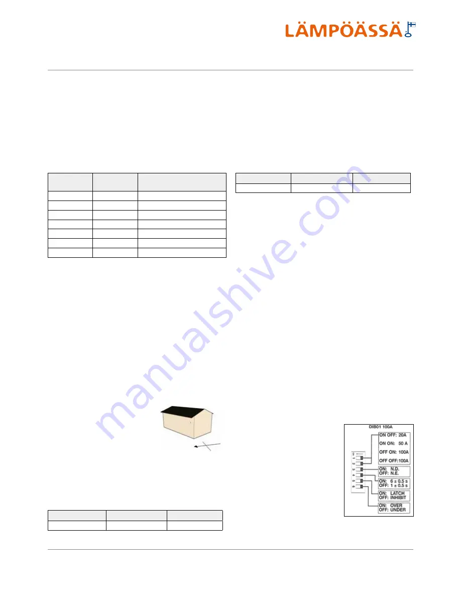
Current monitoring relay installations and connection
These settings are initial and may require changing. Relays must always
be adjusted in a case-specific manner.
•
Choose correct current range
•
Turn switch 2 to position ON (if
master fuse size is less than 50A)
•
Other switches 1, 3-6 to position
OFF.
•
Adjust hysteresis, current % and
delay using screws in the front part
(master fuses 25 A)
•
Hysteresis 21
•
Current 25 - 28 %
•
Delay 1s
•
The relay requires external voltage 24-240 V/AC.
Содержание VMI 6-17
Страница 1: ...L MP SS Vmi 6 17 L MP SS 3 2016 INSTRUCTIONS FOR USE INSTALLATION AND MAINTENANCE...
Страница 31: ...XL 2015 811 2013 A A A B C D E F G A A A B C D E F G Vmi 6 38 dB 00 dB 8 kW 8 kW 8 kW...
Страница 32: ...A A A A A A A A B C D E F G A A A A B C D E F G XL 2015 811 2013 XL X Vmi 6...
Страница 35: ...XL 2015 811 2013 A A A B C D E F G A A A B C D E F G Vmi 9 41 dB 00 dB 10 kW 10 kW 10 kW...
Страница 36: ...A A A A A A A A B C D E F G A A A A B C D E F G XL 2015 811 2013 XL X Vmi 9...
Страница 39: ...XL 2015 811 2013 A A A B C D E F G A A A B C D E F G Vmi 11 36 dB 00 dB 11 kW 11 kW 11 kW...
Страница 40: ...A A A A A A A A B C D E F G A A A A B C D E F G XL 2015 811 2013 XL X Vmi 11...
Страница 43: ...XL 2015 811 2013 A A A B C D E F G A A A B C D E F G Vmi 11 1x230V 41 dB 00 dB 11 kW 11 kW 11 kW...
Страница 44: ...A A A A A A A A B C D E F G A A A A B C D E F G XL 2015 811 2013 XL X Vmi 11 1x230V...
Страница 47: ...XL 2015 811 2013 A A A B C D E F G A A A B C D E F G Vmi 14 38 dB 00 dB 14 kW 14 kW 14 kW...
Страница 48: ...A A A A A A A A B C D E F G A A A A B C D E F G XL 2015 811 2013 XL X Vmi 14...
Страница 51: ...XL 2015 811 2013 A A A B C D E F G A A A B C D E F G Vmi 14 1x230V 43 dB 00 dB 14 kW 14 kW 14 kW...
Страница 52: ...A A A A A A A A B C D E F G A A A A B C D E F G XL 2015 811 2013 XL X Vmi 14 1x230V...
Страница 55: ...XL 2015 811 2013 A A A B C D E F G A A A B C D E F G Vmi 17 42 dB 00 dB 17 kW 17 kW 17 kW...
Страница 56: ...A A A A A A A A B C D E F G A A A A B C D E F G XL 2015 811 2013 XL X Vmi 17...
Страница 60: ......
Страница 61: ......
Страница 62: ......
Страница 63: ......
Страница 64: ......
Страница 65: ......
Страница 66: ......
Страница 67: ......
Страница 68: ......
Страница 69: ......
Страница 70: ......
Страница 71: ......
Страница 72: ......
Страница 73: ......
Страница 74: ......
Страница 75: ......
Страница 76: ......
Страница 77: ......
Страница 78: ......
Страница 79: ......
Страница 80: ......
Страница 81: ......
Страница 82: ......
Страница 83: ......
Страница 84: ......
Страница 85: ......
Страница 86: ......
Страница 87: ......
Страница 88: ......
Страница 89: ......
Страница 90: ......
Страница 91: ......
Страница 92: ......


